Language selection
В настоящее время портал работает - ведутся технические работы.
Catalog

RII MNPO SPEKTR
25 products
View:
Telephone number:
E-mail:
mail@niiin.ru
Website: http://www.niiin.ru
Address:
Russia, Moscow, 35 building.1
Website: http://www.niiin.ru
Address:
Russia, Moscow, 35 building.1
- Selected: 0Areas of use
- Selected: 0Item names
- Selected: 0Manufacturer
- Selected: 0Made in
- Selected: 0Additional
View:
23 products
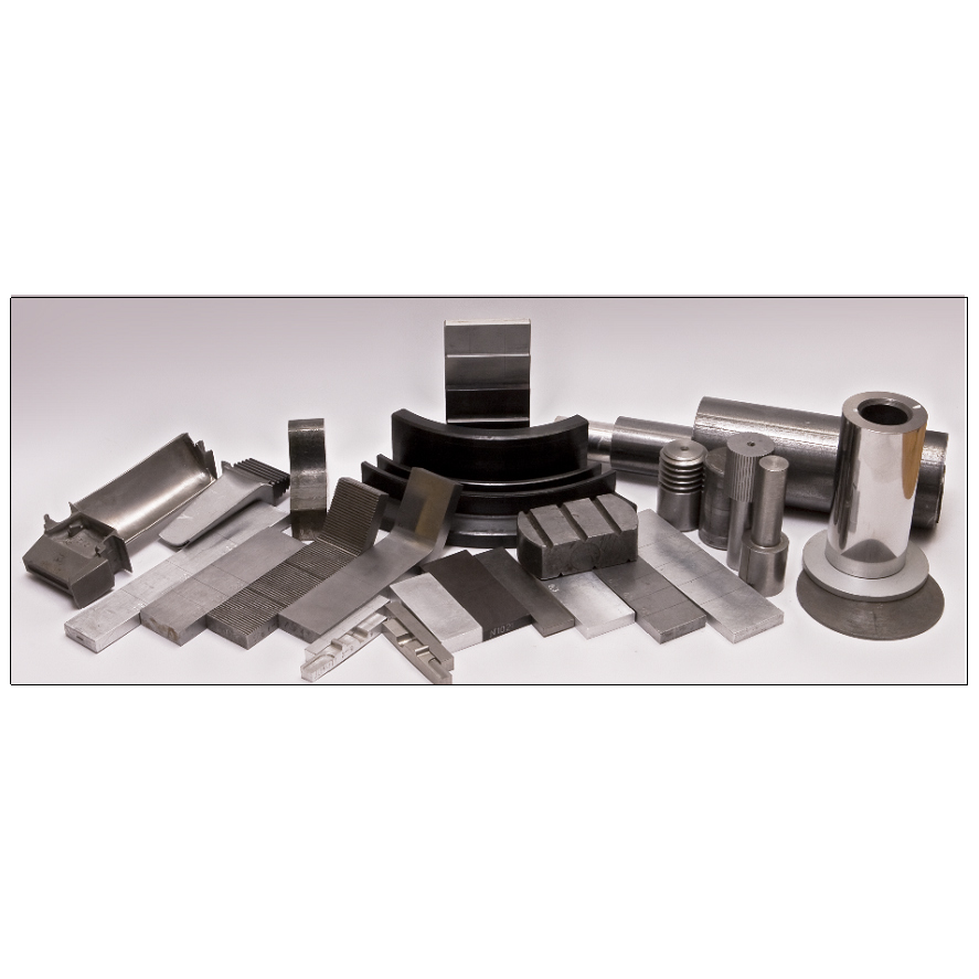
KOIDZ-VD Sets of samples of artificial defects and gaps
from
0 ₽
KOIDZ-VD kits consist of samples of artificial defects (SAD) and samples of gaps (SG). Samples of artificial defects are made in the form of flat and curved plates and cylinders, on the working surfaces of which defects are made in the form of continuity violations like slits of various depths, opening widths and lengths.
The working surfaces of flat SADs are two opposite surfaces on which longitudinal slits are cut by an electroerosion method
The working surfaces of the SAD, reproducing a positive curved surface, are samples with a cylindrical surface.
The working surface of the SAD reproducing negative curvature is the inner surface of the curved plate — the place of inflection.
The KOIDZ-VD kit contains an SAD for determining the influence of various quantities.
To determine the effect of the roughness of the working surfaces, the kit contains SADs with different roughness, on which defects of the same depth are made.
To determine the effect of positive curvature and surface roughness, the kit contains cylindrical samples with different roughness of working surfaces on which defects of the same depth are made.
To determine the simultaneous effect of negative curvature and surface roughness, the kit contains curved plates on which two defects of the same depth are cut, one of which is located on the flat, the other on the curved parts of the sample.
To determine the effect of the chemical composition of the material of the controlled products, the kit contains samples of steel 10, steel 20 and steel 45. The same defects are made on each sample.
To account for the influence of specific electrical conductivity, the kit contains samples from non-magnetic structural materials: aluminum alloy D16T and titanium alloy VT-23. The same defects are made on each sample.
Gap samples are flat and curved plates of different thicknesses made of dielectric material.
Technical specifications
The range of nominal values of the depth of defects, mm: from 0.1 to 10.
The limits of permissible error of the value of the depth of defects, mm: from ± 0.02 to ± 0.25.
The range of nominal values of the width of the opening of defects, mm: from 0.03 to 0.15.
The limits of the permissible error of the width of the opening
of defects, mm: from ± 0.01 to ± 0.05.
The range of nominal values of the length of defects, mm: from 6 to 100.
The limits of permissible error of the value of the length of defects, mm: from ± 0.5 to ± 1.
The range of nominal values of the thickness
of the dielectric gap samples, mm: from 0.2 to 10.
The limits of the permissible error of the thickness of the samples, mm: from ± 0.02 to ± 0.5.
The range of nominal values of the radius of curvature
of curved surfaces with defects, mm:
- convex: from 13 to 510;
- concave: 10.
RII MNPO SPEKTR
Moscow
Produced in: Moscow
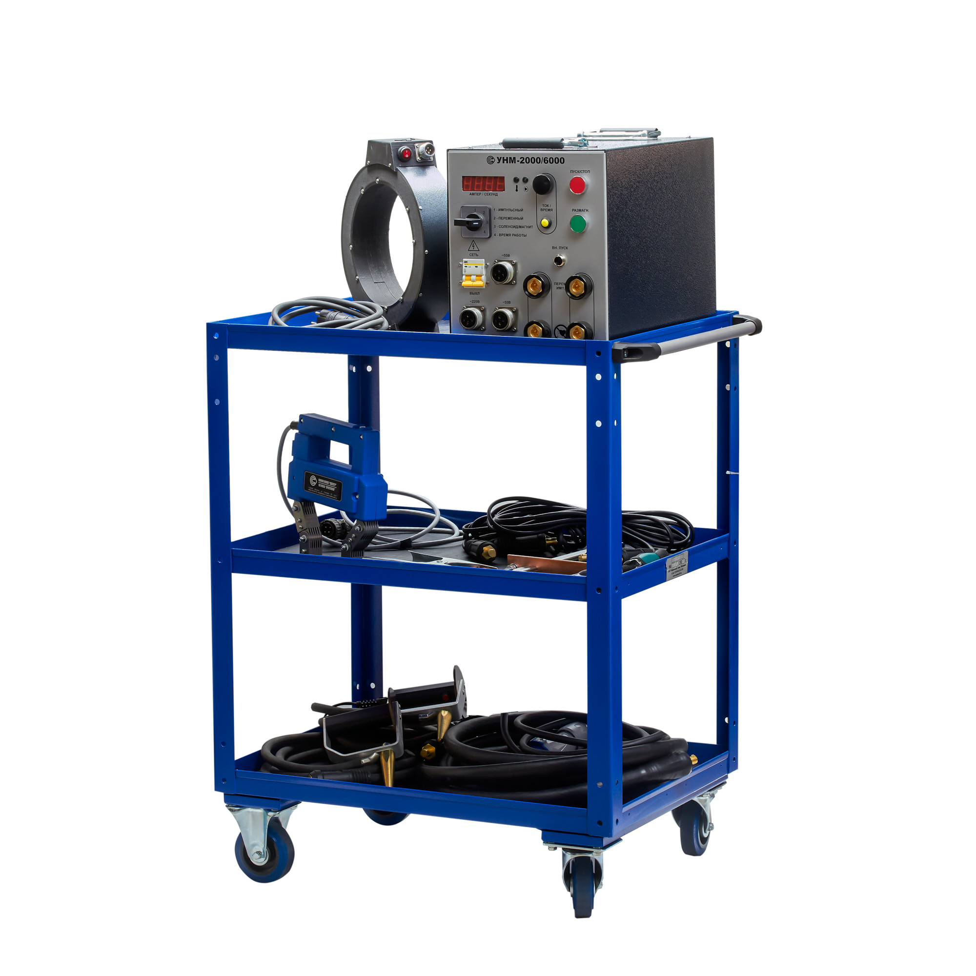
UNM-2000/6000 portable magnetizing device
The principle of operation of the means of magnetic particle control
The portable device UNM-2000/6000 of the MANUL series is a magnetic particle flaw detector that provides measurements by the applied field method and the residual magnetization method using direct, alternating and pulsed current with specified parameters. External magnetizing devices included in the kit (solenoids, electromagnets, contact devices for connecting cables) allow for longitudinal, transverse and circular magnetization of the object under study.
A special magnetic powder, dry or in the form of an emulsion, is applied to the controlled surface. Inhomogeneities of the magnetic field in the places of defects lead to the accumulation of powder particles, thus "showing" a hidden picture.
Design features and advantages of the UNM-2000/6000 powder flaw detector:
In the MANUL series, the UNM-2000/6000 device is capable of providing the highest magnetization current (up to 6000 A in pulse mode), which allows you to control products having a large mass or size, as well as those made of magnetohard alloys;
The device can be included in automated quality control stands: there are network interfaces (LAN, Bluetooth, Wi-Fi) for connection; microprocessor control provides storage and reproduction of magnetization and demagnetization parameters, logging of control results, automatic demagnetization;
The design is modular, allows for changes to implement the individual wishes of the customer;
It fully complies with the following standards: GOST R 56512-2015, GOST R 53700-2009 (ISO 9934-3:2002), GOST R 50.05.06-2018, GOST R ISO 10893-5-2016, GOST ISO 17638-2018 , RD 34.17.102-88, RD-13-05-2006 and other Russian and foreign standards regarding the requirements for magnetizing devices and magnetic particle flaw detectors;
It is approved for use by industry regulatory documents, in particular, by the Russian Railways.
Scope of application
Magnetic powder control devices are widely used in various industries, construction and transport, from steel and pipe rolling plants to organizations engaged in the operation and repair of machines, mechanisms and vehicles. Magnetic powder flaw detectors belong to the means of non-destructive testing and therefore can be used to detect defects in products and structures operating under pressure, including at chemical and oil and gas industry enterprises, as well as during the operation of pipelines.
In particular, devices for monitoring by the magnetic powder method have proven themselves well at Russian Railways and metro enterprises engaged in the operation and repair of rolling stock, including for the control of shafts, wheels and wheel pairs, gearboxes, springs, couplers and other loaded components and parts.
Technical specifications:
Magnetization currents:
Variable,
Pulse,
Rectified (only for solenoid and electromagnet)
The measurement error of the magnetization current is no more than 10%.
Characteristics of the pulse current:
The repetition frequency of unipolar current pulses during magnetization and of multipolar current pulses during demagnetization is (2 ± 0.2) Hz.
The duration of the current pulses is at least 1.5 ms.
Magnetic characteristics of the solenoid:
The maximum alternating magnetic field in the center of a single solenoid is at least 100 A/cm.
The maximum alternating magnetic field on the axis in the center between two solenoids located at a distance of 200 mm is at least 60 A/cm.
The maximum permanent magnetic field in the center of a single solenoid is at least 80 A/cm.
The maximum permanent magnetic field on the axis in the center between two solenoids located at a distance of 200 mm is at least 50 A/cm.
Values of magnetization currents:
The maximum alternating magnetization current in the unwound cable is 6 m × 50 mm2 and on the electrical contacts is at least 2000 A.
The maximum pulse magnetization current in an unwound cable of 4 m × 10 mm2 and on electrical contacts is at least 6000 A.
The current adjustment range in the solenoids and the electromagnet is from 0.5 to 4.5 A.
Characteristics of the electromagnet:
The maximum alternating magnetic field in the air gap of the electromagnet depending on the interpolar distance is as follows:
- in the 140 mm gap: at least 75 A/cm;
- in the 40 mm gap: at least300 A/cm.
The maximum constant magnetic field in the air gap of the electromagnet depending on the interpolar distance is as follows:
- in the 140 mm gap: at least 100 A/cm;
- in the 40 mm gap: at least 400 A/cm.
Operating mode:
The operating mode is cyclic: magnetization/pause.
The magnetization time is adjustable from 1 to 40 s.
The demagnetization time is adjustable from 5 to 60 seconds.
Demagnetization of parts is performed automatically.
The time of setting the operating mode is no more than 15 seconds.
The duration of continuous operation is at least 8 hours.
Power supply parameters:
The device is powered by an AC power supply with a voltage of 220 V and a frequency of 50 Hz.
The power consumed from the network is no more than 5 kVA.
Overall characteristics:
Overall dimensions of the device (w × h × d) – no more than 267×245×465 mm.
The weight of the device is not more than 50 kg.
Other characteristics:
The average worktime before failure is at least 12500 hours.
The average recovery time is no more than 6 hours.
The average service life of the device is at least 10 years.
Сompliance with standards
The device fully complies with the requirements of GOST R 56512-2015, GOST R 53700-2009 (ISO 9934-3:2002), GOST R 50.05.06-2018, GOST R ISO 10893-5-2016, GOST ISO 17638-2018, RD 34.17.102-88 and RD-13-05-2006 in terms of the requirements for magnetizing devices and magnetic particle flaw detectors.
Identification of the load.
It performs automatic identification of the types of connected load: cables, solenoids and electromagnet.
Control of the connected load current
It allows you to control the current of the connected AC/DC electromagnets and solenoids.
The kit includes:
1 Electrical contact with cable, cross section 50 mm2, length 3m
2 Solenoid cable, 3m long
3 Solenoid cable, 0.5m long
4 Magnetizing cable, cross section 10 mm2, length 6m
5 Magnetizing cable, cross section 50 mm2, length 6m
6 Solenoid - 2pcs
7 The electromagnet is manual
8 Trolley
9 Power unit UNM 2000/6000
RII MNPO SPEKTR
Moscow
Produced in: Moscow
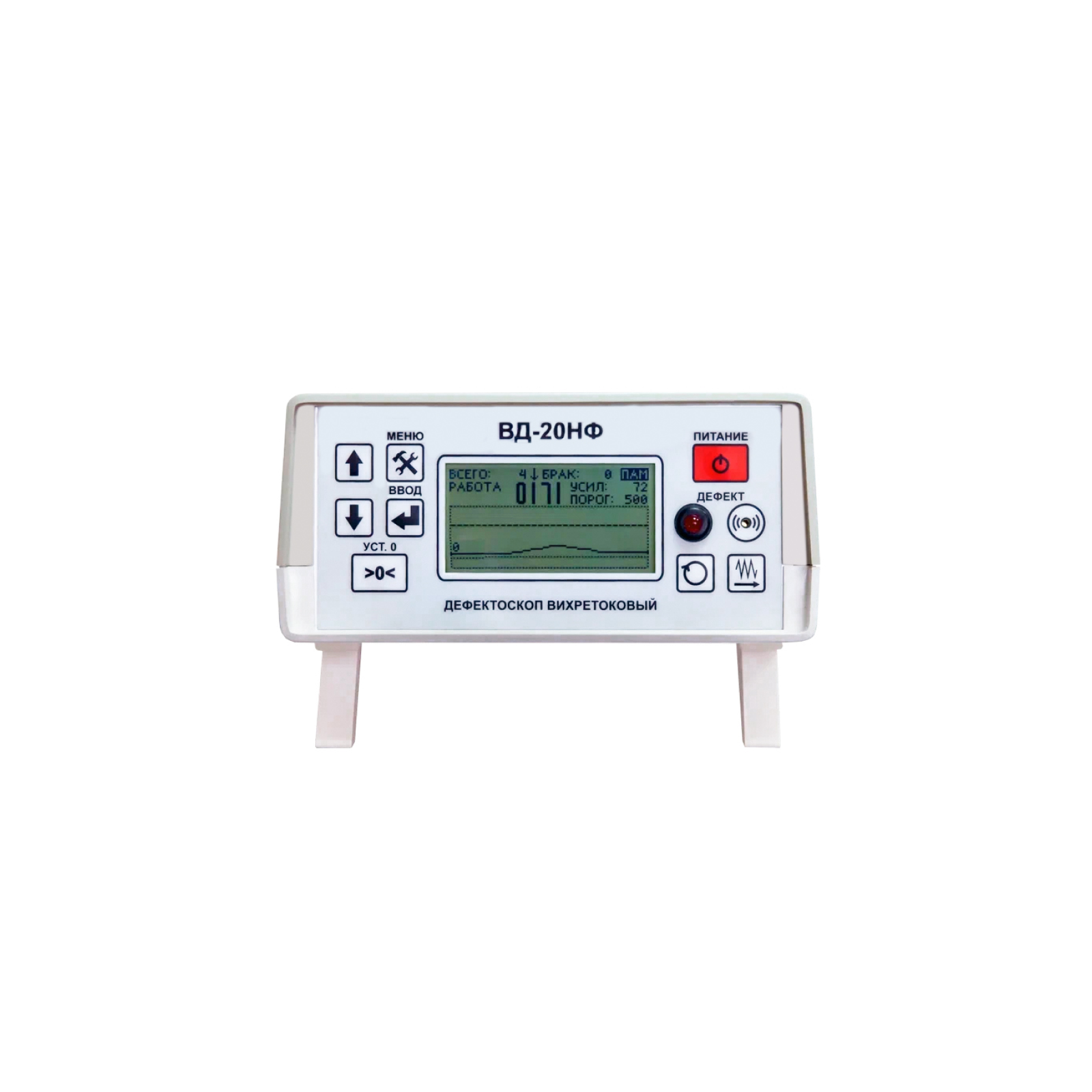
VD-20NF Eddy Current Flaw Detector
The principle of operation of the VD-20NF eddy current flaw detector
The principle of operation of the VD-20NF flaw detector is based on the generation of eddy currents on the surface of the controlled part and subsequent analysis of the signal at the output of the converter, which correlates with the characteristics of the active secondary field.
The device consists of two main blocks: electronic one and electromechanical one, in which an eddy current converter of transformer type is installed. The controlled products (bearing rollers) enter through the input tray into the electromechanical unit of the flaw detector, where they move sequentially and fall under the pressure rollers of the overhead converter holder. The clamping mechanism is adjusted to each size of the rollers, so as to ensure tight contact with the curved surface and fix the tip of the transducer at the required distance from it.
The detection of defects occurs due to the imbalance of the converter when it is located above the surface of the controlled product, caused by the interaction of the primary electromagnetic field generated by the converter with the secondary electromagnetic field of eddy currents induced in the controlled product by the primary field. When cracks are detected, the electronic unit of the flaw detector gives sound and light warning signals, and also triggers the electromagnet of the sorter, which directs the controlled roller into the tray for defective products. In the absence of defects, the controlled roller is directed towards the output tray of the flaw detector.
Design features and advantages
The VD-20NF eddy current flaw detector is equipped with removable input and output trays, power-on switches and a drive for feeding controlled products to the converter, as well as handrails for convenient transportation of the unit.
The mechanisms of the electromechanical unit are protected by a frame made of steel plates. The electronic unit of the flaw detector is portable and can be installed both on the top panel of the electromechanical unit and on the surface of the desktop. Controls and indications of defect detection are located on the front panel of the electronic unit. The delivery package also includes a power adapter for the electronic unit and a tuning sample. The advantages of the VD-20NF flaw detector include:
high reliability (the service life of the flaw detector is more than 10 years);
it is easy to set up and operate;
it has several types of defect detection alarms;
the high probability of detecting defective products (at least 99.9%);
low number of false positives (less than 5%).
Scope of application
According to the current standards of safety and product quality control during repair work in locomotive depots and repair plants, bearing rollers that have passed visual inspection and are recognized as suitable for further operation according to the criteria of geometry and condition of the working surface are subject to mandatory additional control using eddy current flaw detection to detect fatigue cracks invisible during visual inspection on the rolling surface of the rollers. The VD-20NF eddy current flaw detector allows for quality control and automatic disassembly of bearing rollers of various shapes and sizes both in laboratory and factory conditions in full compliance with the requirements of the regulatory documents of Rosstandart and the methods of performing control measurements used in JSC "Russian Railways".
RII MNPO SPEKTR
Moscow
Produced in: Moscow
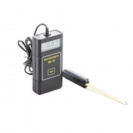
MX-10 Magnetometer
from
80 400 ₽
The MX-10 magnetometer is an auxiliary tool for conducting magnetic powder control using permanent magnets, rectified current electromagnets by the applied field method, as well as for monitoring by the residual magnetization method according to the requirements of the current regulatory documentation.
The MX-10 magnetometer meets the requirements in the field of non-destructive testing for the main industries: nuclear, energy, oil and gas complex, general and special engineering, railway transport, aerospace industry, elevator and crane facilities, etc.
Magnetometer MX-10 is an electronic measuring unit with a remote measuring converter, which is based on the Hall effect. The design of the device allows measuring both the normal and tangential component of the magnetic induction vector directly on the surface of the part. The measured value of the magnetic field induction value is displayed on the digital indicator of the electronic unit.
Features and Benefits
The updated version of the MX-10 magnetometer has a modern element base, which has significantly improved its performance, reduced error and expanded the measurement range (see the Table of Technical characteristics).
The device is capable of operating in two modes:
Constant measurement mode. This is convenient when carrying out a large number of measurements over a short period of time.
Automatic shutdown mode 1 minute after measurement. It allows you to save the charge of the device, which is especially important in the field.
A thermal compensation circuit ensures stable measurement readings at any temperature change.
Other features include:
The small dimensions of the Hall measuring transducer for the MX-10 magnetometer make it possible to measure the induction of the magnetic field in grooves, grooves, angular transitions, i.e. in those areas of the controlled product that are stress concentrators and are most dangerous from the point of view of cracking;
A wide range of measurements of the magnitude of the magnetic field induction;
The smallest measurement error among analogues in the entire operating temperature range;
Convenience of measurement by a remote measuring transducer in various planes;
Low power consumption and, as a result, long working time;
Low cost compared to similar models on the market;
Compact dimensions;
Manufacturer's warranty – 12 months;
The device is included in the state register of measuring instrument RU.C.27.004.A No. 36079 dated 01.09.2009 and has undergone a verification procedure. Magnetometer MX-10 (milliteslameter) it is also included in the register of measuring instruments, test equipment and measurement methods used in JSC "Russian Railways".
Scope of application
1. Verification of the magnetization modes of controlled parts using permanent magnets, rectified current electromagnets by the applied field method, as well as during the control by the residual magnetization method, by measuring the tangential and normal components of the magnetic field strength vector at one or more points on the surface of these parts. The number of points at which the magnetic field strength is measured and their location on the controlled surface depend on the shape of the part, as well as on the type and design of the magnetizing device used.
2. Control of the magnetization of parts before welding. During electric arc welding of non-magnetized parts, the effect of "magnetic blowing" is observed, i.e. the deviation of the electric arc from the axis of the electrode, the wandering of the arc end along the product, which leads to metal splashing during welding, deterioration of the seam quality. Therefore, before welding, it is necessary to measure the level and direction of magnetization of the parts and demagnetize them if necessary.
3. Verification of the residual magnetization after magnetic powder inspection. Demagnetization and verification of the residual magnetization of responsible, rubbing parts, as well as parts in contact with them after assembly, is prescribed in the requirements of the IPC and is a technological stage of control.
4. Magnetization control before assembling various structures. Magnetized parts can affect the operation of automation devices, cause errors in the readings of instruments, equipment. Magnetization can cause the accumulation of wear products in the movable joints, cause a negative effect on subsequent technological operations. Due to possible undesirable consequences, the parts are demagnetized and the quality of their demagnetization is checked.
5. Control of gas and water meters. Housing and utilities enterprises may also be interested in the device. It is known that existing gas or water flow meters can be easily "deceived" with the help of strong permanent magnets that reduce the rotation speed of the flow sensors. There are different ways to detect such theft. One of them is the control of the residual magnetization of the counters using magnetometers. The measured value should not significantly exceed the Earth's magnetic field, otherwise it can be concluded that there was unauthorized interference with the operation of the device.
Main technical characteristics
Measuring range, MT from 0.1 to 100
The limits of the permissible basic absolute measurement error, MT D = 0.02 VI + 0.05,
where VI is the magnetometer readings in MT
Power supply battery type: PP3 (nine-volt battery)
Consumption current, mA, no more than 15
Duration of continuous operation
(from fully charged batteries), h, at least 20
Overall dimensions, mm:
– electronic unit (LxWxH) 120x60x25
– Measuring transducer (Diameter x Length) 18x173
Weight, g, not more than 160
Ambient operating temperature, °C -10...+40
RII MNPO SPEKTR
Moscow
Produced in: Moscow
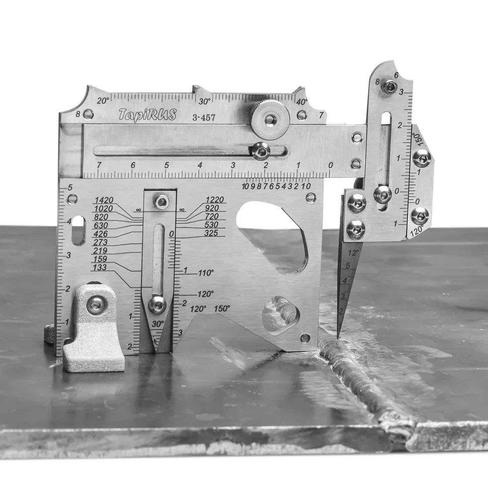
UShS "Tapirus" with cover and supports
from
25 500 ₽
The UShS TapiRus is designed to replace numerous templates and devices used in visual and measuring quality control of welded joints. It is approved as a means of measuring the geometric parameters of welded joints and surface defects during visual and measuring control (VIC) and supplied with verification. It allows you to determine most of the geometric parameters of welded joints and surface defects: the width and convexity of the seam, the depth of the cut, the amount of edge displacement, the angle of the angular seam, the angle of the bevel and the gap, etc. Equipped with supports that allow you to uniquely position the template on a curved surface. To carry out measurements with an error of 0.1 mm, scales with a vernier are applied to the TapiRUS surface. It contains a number of gauges for assessing the smooth transition from the deposited to the base metal, the size of the cathets, radii and angles of cutting edges. Equipped with a probe with a replaceable measuring needle to determine the size of gaps and heights / depressions.
The development, preparation for production and manufacture of TapiRus were carried out exclusively in digital format.
The latest laser and additive technologies are used in the production of TapiRUS:
high-precision laser cutting machines in inert gas;
five-axis CNC machining centers;
ultra-precise color laser engraving of the entire product assembled;
laser stereolithography (SLA) is a technology of layer–by-layer synthesis of a material from a liquid photopolymer.
Advantages
Easy to install. Accurate positioning along the normal to the surface of the object of control and stability of the position when performing measurements.
Functionality. Measurement of most geometric parameters of welded joints and surface defects.
Measurement accuracy. The measurement error on the template scales does not exceed 0.1 mm.
Modernity. Online calculator ergonomic accessories smart version.
More detailed information can be found on the website tapirus.info
MEASURED PARAMETERS AND DEFECTS
VIC at the stage of input control
wall thickness
depth of corrosion ulcers on the base metal
the depth of corrosion ulcers on the weld
the depth of scratches (risks), a bully on the base metal
edge bevel angle
the amount of blunting
geometric parameters of the dent
VIC during assembly (preparation for assembly)
edge offset
withdrawal (angularity) of edges
the gap in the cutting
the height of the potholders
angular displacement
VIC in the welding process (surfacing)
edge offset
height of the root (filling) layer
withdrawal (angularity) of edges
angular displacement
VIC of finished welded joints (structures)
edge offset
angular displacement
the height of the reinforcement of the seam
the height of the bulge (when welding elements of different thickness)
the width of the reinforcement of the seam
withdrawal (angularity) of edges
the depth of the sinking between the rollers
incomplete filling of the cutting edges
scaliness of the seam surface
smooth transition
undercut depth
seam crater depth
technical specifications
Measured parameter Scale Range,mm Error, mm
Depth, mm H 0...20 ±0.1 (in the range 0...10 on), ± 0.5 (in the range over 10...20)
Height, mm H 0...6 ±0.1
Width, mm W 0...55 ±0.1 (in the range 0...10 on), ± 0.5 (in the range over 10...20)
Clearance, mm N 0...5 ±0.1
Dullness, mm F, G 0...25 ±0.5
Specifications
Overall dimensions, mm, no more
(without supports) 115x85x15 ± 0.5
(with supports) 115x85x42 ±0.5
Average time to failure, cycles,
at least 55,000
Weight, kg, not more than 0.22
Average service life, at least 1 year
RII MNPO SPEKTR
Moscow
Produced in: Moscow
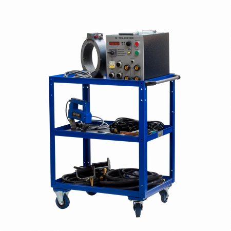
UNM-300/2000 portable magnetizing device
The principle of operation of the magnetic particle flaw detector:
The device provides monitoring and detection of surface defects by the applied field method or by the residual magnetization method.
The kit with the device includes power cables, remote solenoids, and an electromagnet, with which you can produce longitudinal or circular magnetization of the part. A trolley is provided for the transportation of technical equipment and the detection of defects in the field. Magnetization is carried out by alternating, direct or pulsed current of large magnitude, due to which high values of the magnetizing field strength are achieved.
Features and advantages of the UNM-300/2000 magnetic powder control device:
Microprocessor control, which allows you to memorize and accurately reproduce the desired modes and selected measurement parameters, as well as work as part of automated stands and control systems;
The magnetizing device has a digital indicator on the front side and a control panel for selecting the operating mode, type and current strength;
Automatic recognition of the type of connected external magnetizing device;
Device temperature control and automatic shutdown in case of overheating;
Remote connected magnetization devices allow you to control the quality of parts and assemblies of complex shape;
Automatic demagnetization of controlled assemblies and parts;
The equipment meets the requirements of the following standards: GOST R 56512-2015, GOST R 53700-2009 (ISO 9934-3:2002), GOST R 50.05.06-2018, GOST R ISO 10893-5-2016, GOST ISO 17638-2018, RD 34.17.102-88 and RD-13-05-2006;
Devices of the MANUL series (UNM-300/2000 and others) are approved for use by the Russian Railways.
Scope of application:
Magnetic particle flaw detection is indispensable where quality control of various critical and loaded assemblies and parts is required, detection of surface defects that occur during their production, storage and operation.
The device may be in demand:
at factories for the production and repair of automotive, aviation and railway equipment, metro enterprises, military-industrial complex (inspection of shafts, axles, wheel pairs, pistons, beams, springs, etc.);
in civil and military shipbuilding, elevator and crane enterprises (control of rigging equipment, hooks, etc.);
at pipe rolling plants (determination of defects in rolled products);
in the oil and gas, chemical industry (inspection of welds of equipment operating under pressure).
The UNM-300/2000 portable magnetic particle flaw detector has a relatively small weight and dimensions, which allow it to be used as a stationary or portable device in specialized quality control laboratories or in ordinary workshops, garages, hangars, locomotive depots or warehouses.
The UNM 300/2000 device, as well as other means of magnetic powder control, are normally used together with auxiliary equipment for the preparation and application of magnetic powder (suspension), for fixing the indicator pattern, magnetometers for determining residual magnetization, visual inspection means – magnifiers and endoscopes, as well as with ultraviolet irradiators in the case of fluorescent powders.
Technical specifications
Magnetization currents
Variable,
Pulse,
Rectified (only for solenoid and electromagnet)
The measurement error of the magnetization current is no more than 10%.
characteristics of the pulse current
The repetition frequency of unipolar current pulses during magnetization and of multipolar current pulses during demagnetization is (2 ± 0.2) Hz.
The duration of the current pulses is at least 1.5 ms.
Magnetic characteristics of the solenoid
The maximum alternating magnetic field in the center of a single solenoid is at least 100 A/cm.
The maximum alternating magnetic field on the axis in the center between two solenoids located at a distance of 200 mm is at least 60 A/cm.
The maximum permanent magnetic field in the center of a single solenoid is at least 80 A/cm.
The maximum permanent magnetic field on the axis in the center between two solenoids located at a distance of 200 mm is at least 50 A/cm.
Values of magnetization currents
The maximum alternating magnetization current in the unwound cable 6 m × 50 mm2 and on the electrical contacts is at least 1000 A.
The maximum pulse magnetization current in an unwound cable of 4 m × 10 mm2 and on electrical contacts is at least 2000 A.
The current adjustment range in the solenoids and the electromagnet is from 0.5 to 4.5 A.
Characteristics of the electromagnet
The maximum alternating magnetic field in the air gap of the electromagnet depending on the interpolar distance is as follows:
- in the 140 mm gap: at least 75 A/cm;
- in the 40 mm gap: at least 300 A/cm.
The maximum constant magnetic field in the air gap of the electromagnet depending on the interpolar distance is as follows:
- in the 140 mm gap: at least 100 A/cm;
- in the 40 mm gap: at least 400 A/cm.
Operating mode
The operating mode is cyclic: magnetization/pause.
The magnetization time is adjustable from 1 to 40 s.
The demagnetization time is adjustable from 5 to 60 seconds.
Demagnetization of details is performed automatically.
The time of setting the operating mode is no more than 15 seconds.
The duration of continuous operation is at least 8 hours.
Power supply parameters
The device is powered by an alternating current network with a voltage of 220 V and a frequency of 50 Hz.
The power consumed from the network is no more than 5 kVA.
weight and size characteristics
Overall dimensions of the device (w × h × d) – no more than 267×245×465 mm.
The weight of the device is not more than 50 kg.
Other characteristics
The average worktime before failure is at least 12500 hours.
The average recovery time is no more than 6 hours.
The average service life of the device is at least 10 years.
Compliance with standards
The device fully complies with the requirements of GOST R 56512-2015, GOST R 53700-2009 (ISO 9934-3:2002), GOST R 50.05.06-2018, GOST R ISO 10893-5-2016, GOST ISO 17638-2018, RD 34.17.102-88 and RD-13-05-2006 in terms of the requirements for magnetizing devices and magnetic particle flaw detectors.
Identification of the load.
It performs automatic identification of the types of connected load: cables, solenoids and electromagnet.
Control of the connected load current
It allows you to control the current of the connected AC/DC electromagnets and solenoids.
RII MNPO SPEKTR
Moscow
Produced in: Moscow
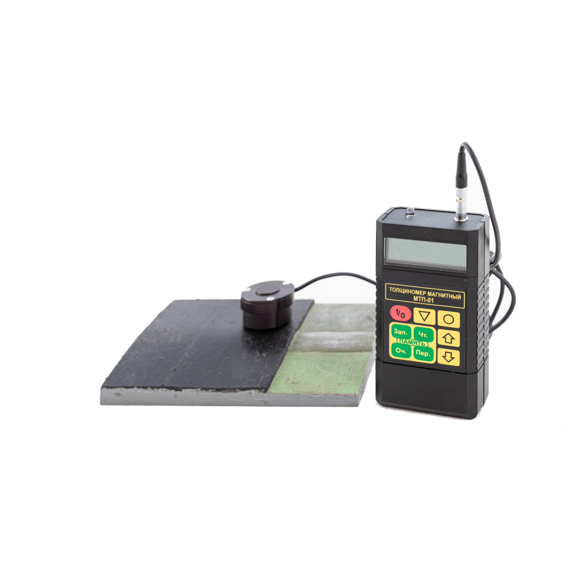
MTP-01 Magnetic Coating Thickness Gauge
from
90 000 ₽
Measuring range of thickness of protective coatings, mm: from 0.2 to 10
Digital display of measurement results: yes
Power supply: from a PP3 type
battery with a voltage of 9V
Power consumption, MW: 100
Operating mode setting time, min: 1
Time of one measurement, sec: 3
Memory capacity, number of thickness values: 2000
Overall dimensions, mm:
- electronic unit (width-depth length) 120x60x25
- measuring transducer (diameter height) 33x23
- connecting cable (length) 1500±300
Weight, g, no more:
- electronic unit (without battery power) 80
- measuring converter 40
The kit includes:
- Electronic unit,
- Measuring converter
- Plate made of non-magnetic material for setting the upper limit of measurements
- Battery type PP3
- CD-ROM with the program
- Prism
- Cover
- Spring
- Case
- Passport
- Operation Manual
RII MNPO SPEKTR
Moscow
Produced in: Moscow
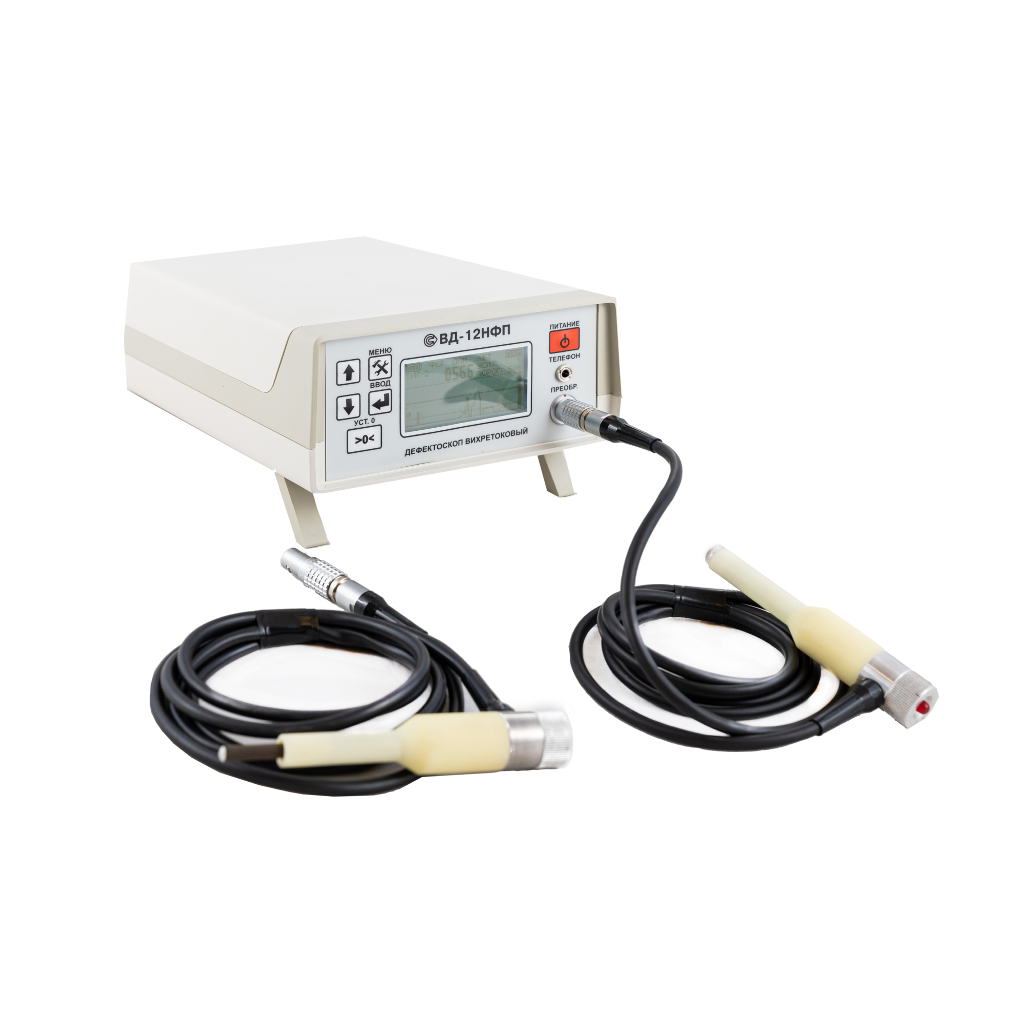
VD-12NFP Eddy Current Flaw Detector with 2 converters
from
292 500 ₽
The device allows you to detect surface defects like cracks, visualizing the signal from the continuity interruptions on the display. The design of the flaw detector allows to determine with high reliability the exact location and depth of defects even on rough surfaces of flat and curved shape, including under a layer of corrosion or in the presence of a protective coating of the controlled area of the product with a thickness of up to 3 mm.
The principle of operation of the VD-12NFP eddy current flaw detector:
The principle of operation of the VD-12NFP eddy current flaw detector is based on the phenomenon of electromagnetic induction. An alternating magnetic field created in the primary coil of the converter by means of a sinusoidal voltage generator excites eddy currents in the controlled product. A parasitic magnetic field formed by eddy currents at the locations of defects affects the measuring unit (two signal coils connected in series) of the converter, creating an electromotive force in it. The amplitude and phase of the secondary signal carries information about the properties of the defect and the position of the transducer relative to the surface of the controlled product. The output signal from the measuring unit of the converter, after amplification and processing using a microprocessor, is displayed on the readout of the device, and is also stored in the memory block for subsequent transmission to a personal computer. In addition, information about the defects is displayed on a piezoelectric bell used as an audio indicator.
Design, features and advantages of the VD-12NFP eddy current control device:
The VD-12NFP eddy current flaw detector is a portable device capable of working both in a desktop and in a suspended position in a special bag-case. This ensures convenient operation of the device in a variety of conditions: in the laboratory, in the factory shop or during field tests. The flaw detector consists of an electronic unit with controls and display of test results, as well as three replaceable converters with wear-resistant corundum tips connected to the electronic unit using a connector. The choice of the desired converter depends on the magnetic properties of the material. For the control of parts with grooves, a converter with an inclined tip is offered. The device is powered by 4 AA batteries located in the battery compartment of the electronic unit.
The advantages of the flaw detector include:
- a screen for visualizing the signal during measurement;
- light weight and compact dimensions that allow you to use the device in almost any conditions;
- the ability to control the quality of products of various curvature and surface roughness even in the presence of a protective coating or a layer of corrosion;
- wear resistance of converters, which is important when monitoring products with increased surface roughness (up to Rz£320);
- automatic detection of the type of converter when connected, as well as the presence of built-in memory for storing control results;
- the possibility to transfer data to a personal computer for storing or printing control protocols.
Scope of application:
Portability, high productivity, the ability to work with curved and rough surfaces, as well as the fact that the operation of the flaw detector is practically unaffected by humidity, pressure and contamination of the gas environment or the surface of the controlled product with non-conductive substances ensure the versatility of the device for detecting cracks in various materials.
The eddy current flaw detector VD-12NFP is actively used in heavy industry for diagnostics of metal structures, assemblies and mechanisms for various purposes in factory workshops or laboratories, including at enterprises of railway transport, automotive industry, mechanical engineering, pipelines and metal structures.
The VD-12NFP flaw detector can be used with equal success in the field, factory workshops, depots, laboratories and workshops to monitor the current condition, as well as to assess the degree of wear, the possibility and duration of further operation of such products made of metals and alloys as over-spring beams, wagon wheels, auto coupler housings, side frames, wheel couples and others.
Distinctive features:
• control of parts with surface roughness up to Rz320 due to wear-resistant corundum tips;
• assessment of the degree of danger (depth) of the defect;
• automatic detection of the converter type;
• microprocessor control;
• 5 universal programs for saving settings;
• capable of detecting defects with a depth of 0.3 mm
• The angle of deviation of the converter from the normal to the working surface up to 60°
• Operating frequency of 70 kHz;
• Maximum working clearance of 3mm;
• visualization of the signal from the defect;
• built-in memory for storing control results
• Equipped with a Bluetooth 2.0 wireless communication module, which allows you to transmit control results and control the flaw detector at a distance of up to 20m;
• The possibility of forming a control protocol based on the data transmitted to the PC;
• Temperature range from 0°C to +40°C;
• The design allows you to work with the flaw detector without removing it from the bag-case.
Basic kit:
Ia5.173.016: 1 electronic unit
Ia5.125.031: 1 converter, type 1; marked as (•)
Ia5.125.030: 1 converter, type 2; marked as (••)
Ia2.706.002: the KOIDZ-VD set of samples with a passport (consisting of:
Ia8.896.034: 1 piece;
Ia8.896.035: 1 piece;
Ia8.896.035-01: 1 piece) - A certificate of verification.
4 AA batteries
1 charger
1 small-sized phone
1 CD with software
1 special key
1 bag-case
A calibration certificate is issued for the VD-12NFP flaw detector.
1 passport
1 operating manual
1 calibration instruction
RII MNPO SPEKTR
Moscow
Produced in: Moscow
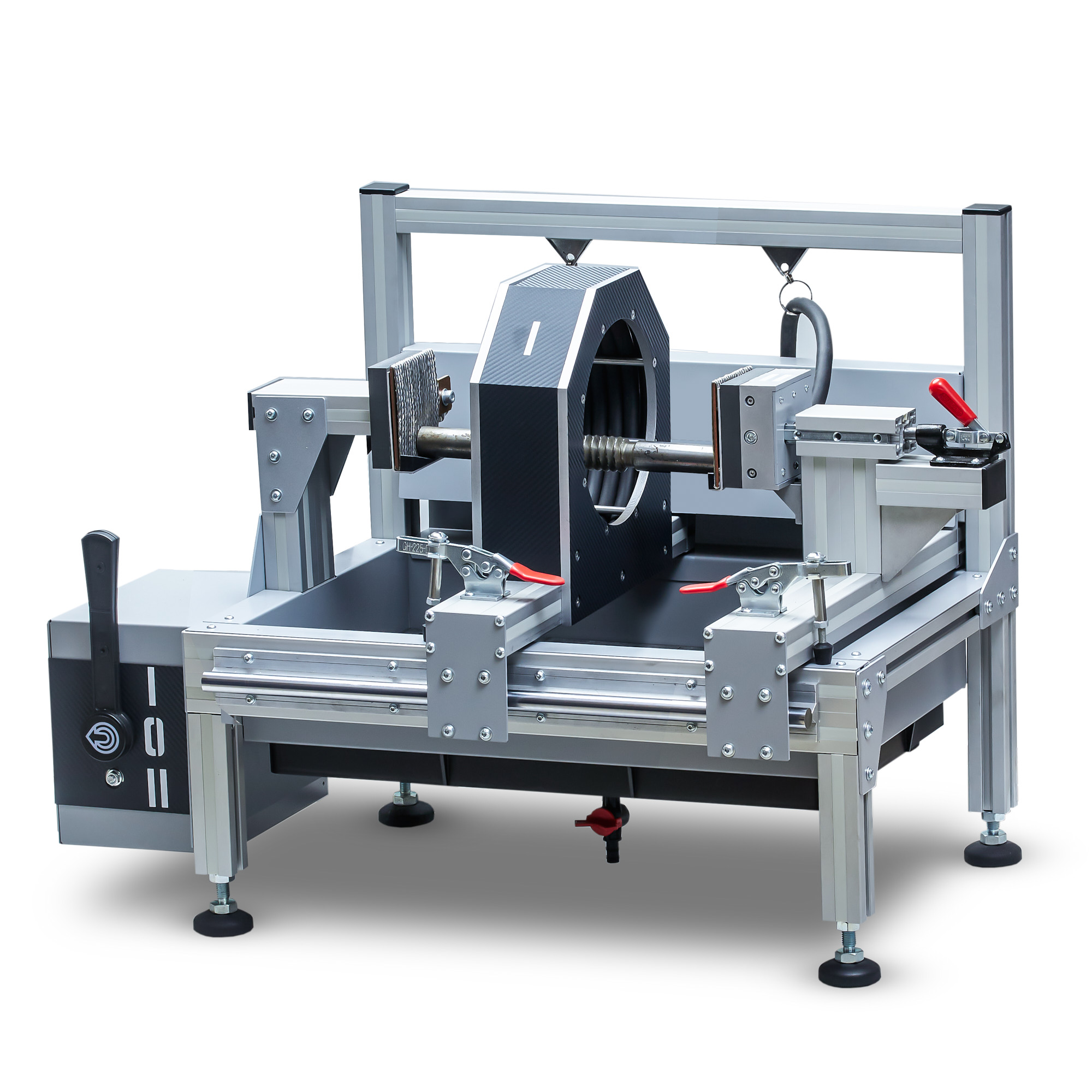
Magnetic powder control stand
The magnetic particle testing stand has a simple switch between circular and longitudinal magnetization modes, as well as easy movement and fixation of the solenoid and electrical contact for locating the test object in the working area of the stand.
Clamping of the controlled part during circular magnetization occurs in one movement.
The stand can be installed on a stationary or mobile magnetic particle testing station. For ease of inspection after magnetization, a tray with a removable protective grid is provided. The protective rear wall protects against the spread of spray splashes outside the working area.
RII MNPO SPEKTR
Moscow
Produced in: Moscow
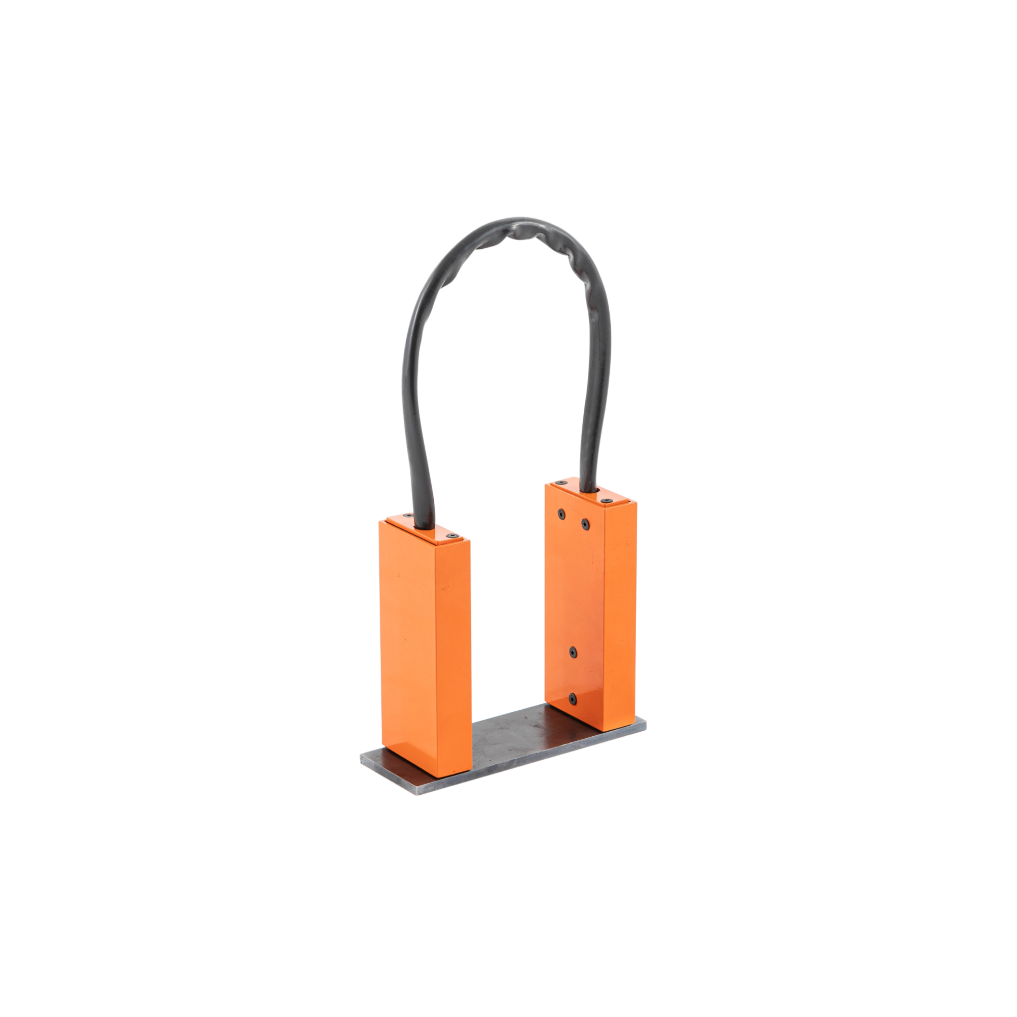
UN-5 Magnetizing device
from
95 550 ₽
The principle of operation of the magnetization device:
The device consists of two compact blocks made of non-magnetic material connected by a flexible magnetic circuit. In each block there is a permanent magnet made of neodymium-iron-boron alloy (Ne-Fe-B). When installing the blocks on the surface of the part, a closed magnetic circuit is formed with the direction of the magnetizing field from one pole to the other. Above the defect scattering fields, magnetic powder particles are deposited to form an indicator pattern.
Design features and advantages of the device for magnetic particle control UN-5
The delivery package with the device includes a portable case, an inter-pole jumper installed during transportation, and a liner for fixing blocks with permanent magnets.
The UN-5 portable device does not require electrical power and therefore can be used where the supply of stationary power is difficult or impossible under regulatory documents: in the field, when working at height, for inspection of capacitive equipment operating under pressure, etc.
- The device is easy to use, lightweight and small-sized, working with it does not require special physical and technical training from the operator;
- Flexible magnetic core allows you to use the device to control parts of complex shape;
- The UN-5 magnetizing device is distinguished by an increased quality of the indicator pattern and an increased control zone due to a reduced uncontrolled zone near the poles and an improved ratio of the normal and tangential components of the magnetic field (Russian patent No. 60732);
- The technical characteristics of the device comply with Russian and foreign regulatory documents, this being the reason of its widespread use in more than 40 countries, including Germany, France, Brazil and Norway.
When monitoring, the controlled area is the central part of the area located between the magnetic poles of the device.
The width of the monitored area is determined by the width of the magnetic poles of the device and is approximately 60 mm. The length of the monitored section depends on the inter-pole distance.
the dimensions of the controlled area are given depending on the device's inter-pole distance:
Inter-pole distance, mm 95: 75 55
Controlled area between the working poles, mm: 60x60 40x60 25x55
The length of the defect detection zone depends on the distance established between the working poles of the magnet on the controlled product.
Defects are not detected in the areas adjacent to the poles of the magnet. The length of these sections is 18 mm with an interpolar distance of 95 and 75 mm. With an interpolar distance of 55 mm these sections are 13 mm long.
Scope of application:
Magnetizing devices for magnetic powder flaw detection are used in many industries, including railway, water and aviation transport, in the construction and operation of pipelines, in chemical and petrochemical production.
The flexible link between the magnetic blocks allows the control of products of complex shape, for example, cylindrical tanks, high-pressure apparatuses, main pipelines, etc.
When checking for defects, the device can be used together with other auxiliary equipment for:
- preliminary and subsequent demagnetization;
- application of a magnetic indicator (which can be dry or in the form of an emulsion);
- magnetoluminescent control (with ultraviolet lamps).
RII MNPO SPEKTR
Moscow
Produced in: Moscow
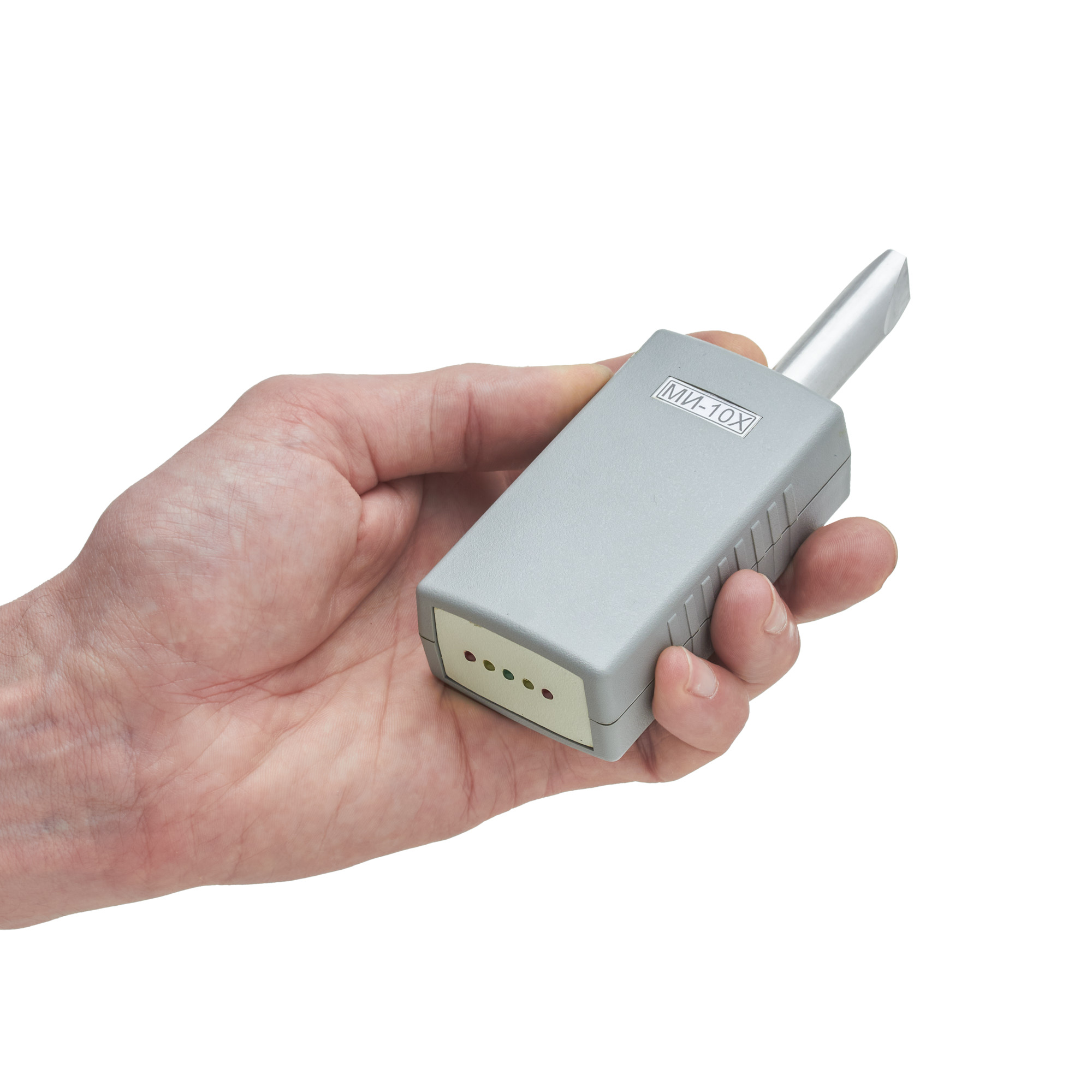
MI-10X Magnetic Indicator
from
22 500 ₽
Distinctive features.
Compactness
Autonomy
Maximum ease of handling
Energy saving mode
Technical specifications
Indication of induction levels, MT,:
weak magnetization 0...2
average magnetization 2...10
strong magnetization more than 10
Power supply 1 accumulator unit or PP3 battery
Current consumption, mA, no more than 8
Operating temperature range, °C -30...+50
Dimensions of the electronic unit, mm 90x50x32
Dimensions of the converter, mm 14x50
RII MNPO SPEKTR
Moscow
Produced in: Moscow
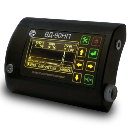
VD-90NP Eddy current flaw detector in the basic configuration
from
398 250 ₽
The principle of operation of the device:
The principle of operation of the flaw detector is based on the excitation of eddy currents in the controlled product and the subsequent release of a signal at the output of the converter, the amplitude and phase of which are determined by the secondary field of eddy currents.
Design features and advantages of the VD-90NP flaw detector.
The device has a small-sized case, which ensures its lightness, ergonomics and allows you to mount it on your belt or on your arm. The measurement is performed using a remote converter connected by a flexible cable. There are several types of converters for eddy current flaw detection of products made of different materials and different geometries. The large and bright display displays the selected operating modes and measurement results in text and graphic form. The VD-90NP is also characterized by:
high sensitivity (it detects cracks starting from 0.1 mm in size);
dust–and-moisture-proof housing, which makes it applicable for work in the field;
large operating frequency range;
maximum working clearance up to 10mm;
Bluetooth connection;
the ability to control products with high surface roughness, up to Rz320 class;
light and sound indication of defect detection;
wide operating temperature range from –30°C to +50°C;
autonomous low-voltage power supply;
long continuous operation time from one set of batteries;
compliance with the standard GOST R ISO 15549-2009 (ISO 15549:2008).
The use of a microprocessor-based hardware and software platform provide it with the following operational characteristics:
automatic adjustment when measuring conditions change, including compensating the influence of the gap;
built-in calibration modes;
saving the measurement results in the internal memory of the device;
a large number of stored programs: sets of parameters and measurement modes, both preset and saved by the user so as to repeatedly monitor the same type of products;
The Bluetooth 2.0 wireless communication module allows the device to be used in conjunction with an external laptop or mobile device for remote control, transmission of measurement results for further storage, printing, documentation and analysis.
Scope of application:
The eddy current method is suitable for non-destructive testing and detection of microcracks in products and parts made of any metals and alloys of complex shape, with high surface roughness, through non-conductive coatings, as well as for checking welded joints. The flaw detector can be used to control parts and assemblies of aviation equipment.
The VD-90NP eddy current flaw detector is used for quality control and preventive examination of:
- components and parts of rolling stock at railway transport enterprises: wheel sets, auto coupler housings, side frames, spring beams, labyrinth rings, pulleys;
- pipes, profiles, rods at rolling mills at the output control, and at the input control of consumers of products;
- products made of aluminum and titanium alloys with multilayer coatings at enterprises of the aviation and aerospace industry;
- cables, beams, critical components of equipment (cranes, lifts) in construction;
- main pipelines in order to detect stress corrosion.
A wide range of operating temperatures, dust and moisture protection (IP54 degree of protection), autonomous low-voltage power supply, a long time of continuous operation of the device allows it to be used in the field at low temperatures and under precipitation (rain, snow).
Basic kit:
• 1 electronic unit for the VD-90NP eddy current flaw detector;
• 1 Ia5.125.052 (Type-2) eddy current converter;
• 1 converter cable;
• 1 charger with batteries;
• 1 hand strap;
• 1 Ia8.896.104 sample with artificial defects;
• 1 Ia8.896.035 coating sample;
• 1 storage and carrying case;
• 1 documentation set.
RII MNPO SPEKTR
Moscow
Produced in: Moscow