Catalog

Equipment
Магнетрон с круглой мишенью 2 дюйма
from
275000.00
Институт физики им. Х.И.Амирханова
Махачкала
Metrology
525 products
View:
- Selected: 0Areas of use
- Selected: 0Item names
- Selected: 0Manufacturer
- Selected: 0Made in
- Selected: 0Additional
View:
525 products
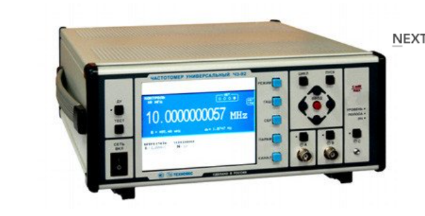
Universal frequency meter Ch3-92
The frequency meter is able to work both independently and as part of automated measuring systems with interfaces such as USB or RS-232.
Technical specifications
Frequency and period of sinusoidal signals (inputs A, B) 0.001 Hz - 300 MHz
Frequency and period of video pulse signals (inputs A, B) 0.001 Hz - 300 MHz
Frequency of continuous sinusoidal oscillations (input C) (0.3 – 37.5) GHz
Pulse duration 10 ns - 1000 s
The duration of the front, the decay of the pulses is 5 ns - 100 microseconds
Time interval from -1000 to 1000 s
Frequency measurement resolution 2x10⁻¹⁰ s/Rng
The range of setting the trigger levels (inputs A, B) from minus 2.5 to 2.5 V
The error of setting the trigger levels (inputs A, B) ± 0.05 V
Input signal level:
• for sinusoidal signal (inputs A, B) (0.03 - 10.0) V
• for video pulse signal (inputs A, B) (0.1 - 10.0) V
• for sinusoidal signal (input C) 50 MW - 5 MW
Input resistance
• Inputs A, B (50±2.5) ohms; (1±0.1) MOm/100 pF
• Input With (50±2.5) ohms
Nominal frequency value of the reference quartz oscillator 10 MHz
Relative error in the frequency of the quartz oscillator, no more than ± 2x10⁻⁷ in 12 months
Operating temperature range from minus 10 to 40 °C
AC power supply 220 V, 50 Hz
Power consumption, not more than 100 VA
Overall dimensions, mm
299x136x436,5
Weight, not more than 8.5 kg
TEKHNOYAKS
Moscow
Produced in: Moscow
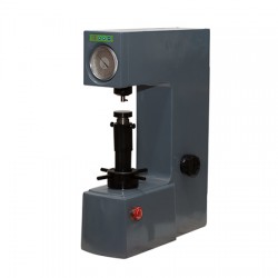
Metolab 101 Rockwell Hardness Tester
METOLAB 101 is an analog stationary hardness tester according to the Rockwell method, a modification of the METOLAB 100 hardness tester with an electromechanical loading system. The rest of the devices are identical.
The stationary METOLAB 101 hardness tester is designed to measure the hardness of various materials using the Rockwell method, HRA, HRB and HRC scales. Due to its ease of operation, the stationary METOLAB 100 hardness tester can find its application in a wide variety of industries and production, as well as in educational institutions of various levels in the training of specialists.
The stationary METOLAB 101 Rockwell hardness tester is included in the State Register of Measuring Instruments of Russia (GRSI) and comes with a certificate of primary verification (on request). The number in the GRSI is 65128-16.
Distinctive features of the stationary METOLAB 101 Rockwell hardness tester:
Simplicity and convenience in both operation and maintenance;
Wide range of measured values;
High degree of reliability;
Low cost of measurements compared to competitors.
Basic delivery package:
Stationary METOLAB 101 hardness tester;
Indenter with a ball (1.5875 mm) - 1 pc.;
Conical diamond indenter (120°) - 1 pc.;
Flat table SP1 (60 mm);
V-shaped prismatic table SRP1 (40 mm);
Rockwell hardness measures - 1 set;
User Manual.
Additional information: GOST standards and regulatory documents establishing requirements for the METOLAB 101 Rockwell hardness tester:
GOST 8.064-94 GSI. State verification scheme for hardness measuring instruments on the Rockwell and Super-Rockwell scales;
GOST 9013-59 Metals and alloys. Rockwell hardness measurement method. Scales A, B, C;
GOST 22975-78 Metals and alloys. Rockwell hardness measurement method at low loads (Super-Rockwell);
GOST 23677-79 Hardness testers for metals. General technical requirements.
Metolab
Moscow
Produced in: Moscow
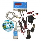
Central Heating Unit Kit
The kit is designed to control the temperature and pressure of the coolant and archive the measured results for further documentation and analysis. The main purpose of the kit is to control the coolant parameter, monitor the pressure and pressure drop between the supply and return pipelines, and fix hydraulic shocks.
Features of the CTP kit
The CTP kit allows you to control the parameters of the coolant supply, temperature and pressure.
The kit consists of a four-channel meter-recorder, which allows you to store 15,000 values in memory for each channel with an interval of 5 seconds. up to several hours, which allows you to take measurements and store data for up to 1 year.
The CTP kit allows you to monitor temperature and pressure around the clock throughout the year, and if necessary, for a longer period. With the help of the CTP kit, we see all the dynamics of the development of the situation of changes in temperature and pressure of the coolant, including weekends (crimping, stopping, starting the heating network, operating modes).
The kit allows you to increase the responsibility of personnel for compliance with technological regimes. There is a real-time indication that allows personnel to monitor the parameters of the supplied coolant.
A set of TTP is usually installed at the border of responsibility, i.e. at the point where, according to the contract, the supplier is obliged to supply a certain amount of coolant with a specific temperature and pressure parameters.
TEKHNO-AS
Kolomna
Produced in: Kolomna, Moscow region
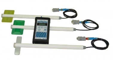
Field strength meter small-sized microprocessor IPM-101M
Purpose:
The device is designed to monitor compliance with the maximum permissible levels of high-frequency radiation (alternating electric field strength, alternating magnetic field strength and electromagnetic field energy flux density) at the workplaces of personnel servicing electrical and radio engineering installations and systems emitting an electromagnetic field, in accordance with GOST 12.1.006, GN 2.1.8./2.2.4.019 and San-PiN 2.2.4/2.1.8.055.
Doza
Zelenograd
Produced in: Moscow
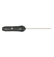
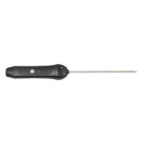
Submersible smart probe L=150 mm SZPG.150M (d=2 mm)
from
11 454 ₽
The submersible smart probe L=150 mm SZPG.150M (d=2 mm) is designed to measure the temperature of various materials by direct contact of the probe with the measuring object and transmitting the measured value via Bluetooth to devices with the installed ThermoMonitor, Android program.
Operating conditions of the SZPG.150M smart probe
Ambient temperature, °C: -20...+55.
Relative humidity, %: not more than 80 at T=35 °C.
Atmospheric pressure, kPa: 86...106.
Functionality of the SZPG.150M smart probe
Measurement of physical quantities with a resolution of 0.01.
Recording of measured values at intervals from 5 seconds to 23 hours 59 minutes 59 seconds (only smart probes with built-in memory).
Transmitting data about measured physical quantities via Bluetooth to a device with the ThermoMonitor, Android program installed.
Transmitting information about the state of charge of the built-in battery via Bluetooth to a device with the ThermoMonitor, Android program installed.
Automatic transition to sleep mode after 50 seconds.
The ability to connect external power.
Possibility of calibration.
TEKHNO-AS
Kolomna
Produced in: Kolomna, Moscow region
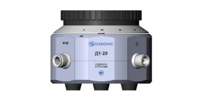
Measuring step attenuator D1-29
The device replaces the devices for checking the attenuators D1-13A and D1-25.
D1-29 is a step attenuator with a range of attenuation from 0 to 110 dB with a step of 10 dB, operating in the frequency range from 0 to 150 MHz.
The device consists of a housing with damping cells and a switch with a counting device. The housing contains coaxial input and output connectors, as well as additional connectors "40 dB" and "80 dB", necessary for the verification of the device.
Technical specifications
Operating frequency range 0 – 150 MHz
Difference attenuation setting range (after 10 dB) 0 – 110 dB
Input electrical resistance to direct current 50 ± 0.1 ohms
The output electrical resistance to direct current when connected to the load input is 50 ± 0.1 ohms 25 ± 0.1 ohms
The main absolute error of the difference attenuation setting relative to the 0 dB mark at direct current ± (0.002 - 0.02) dB
The main absolute error of the difference attenuation setting relative to the 10 dB mark in the frequency range up to 30 MHz ± (0.004 - 0.9) dB
The main absolute error of the difference attenuation setting relative to the 10 dB mark in the frequency range over 30 to 150 MHz ± (0.09 - 3.0) dB
The maximum permissible value of the electrical voltage (DC or AC) at the input of the attenuator 3 In
the operating temperature range from 5 to 40 ° C
Overall dimensions, mm 149x95x149
Weight, not more than 3 kg
TEKHNOYAKS
Moscow
Produced in: Moscow
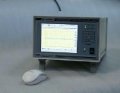
Frequency comparator CHK7-1011
Frequency comparators CHK7-1011 and CHK7-1011/1 can also be used as frequency and time standards with frequency correction based on GLONASS/GPS signals as sources of highly stable signals in various frequency measuring systems.
Comparators have a built-in device for processing measurement data based on a microcomputer, which provides statistical processing of the results of frequency and time measurements, and a device for displaying information based on a color TFT display. The built-in diagnostic system allows you to quickly determine the operability and condition of the main comparator devices with information output to the built-in display screen.
Comparators are available in three versions and differ in composition and functions performed. Comparators have a basic set of devices (modules), including a frequency comparator, a power supply module and a device for processing and displaying information based on a microcomputer and a color TFT display.
The frequency comparator CHK7-1011 has a built-in SRNS receiver and a highly stable rubidium frequency standard Ch1-1014 with the function of correcting the actual frequency value by signals from satellite radio navigation systems GLONASS or GPS. The comparator forms its own time scale with the ability to synchronize on any external time scale received by the SRNS receiver built into the device. The device has two modes for measuring the deviation of the generated time scale: from the time scale of the built-in SRNS receiver and from the external time scale. Information about the current time received from the SRNS receiver is displayed on the comparator display screen, and is also transmitted to the consumer via the RS-485 interface.
All the above-mentioned features make the frequency comparator CHK7-1011 a unique measuring device in the field of frequency and time measurements.
The frequency comparator CHK7-1011/1 has a highly stable rubidium frequency standard Ch1-1013 and can be used as a frequency and time standard as a source of highly stable signals in various frequency measuring systems.
The frequency comparator CHK7-1011/2 does not include any additional devices. To carry out measurements with it, it is necessary to use a highly stable signal of the reference frequency from an external RF or hydrogen frequency standard.
For the convenience of users, apart from the keypad, they can also exercise control of the functions of the devices with a mouse-type manipulator included in the delivery package. Comparators provide access to measurement data over an Ethernet network.
Ruknar
Nizhny Novgorod
Produced in: Nizhny Novgorod
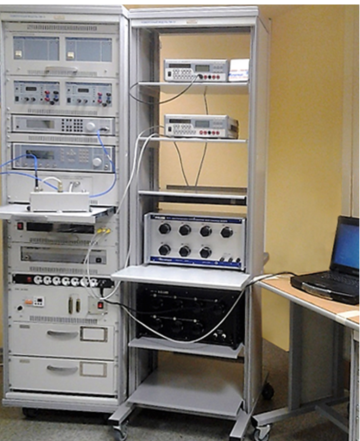
Verification module PM-10
The composition of the PM-10 verification module:
Wattmeter of passing power M2-35;
Complex transmission and reflection coefficients meter "OBZOR-804/1";
Universal voltmeter V7-81 (2 pcs.);
High-frequency signal generator G4-229;
High-frequency signal generator G4-230;
DC power supply B5-79/1 (2 pcs.);
AC power source B2-7 (2 pcs.);
The measure of DC electrical resistance is multi-valued MS3070-3, CT 0.005;
The measure of DC electrical resistance is multi-valued MS3055, CT 0.02;
Single-digit electrical resistance measures MS3080 (0.1; 1 ohm, CT 0.005);
Thermoelectric voltage converter 0.5 V;
Kit for measuring coaxial connectors KISK-7M;
PC, printer;
Basic load-bearing structures (BNC).
Technical specifications
Measuring ranges of electrical and radio engineering quantities:
Operating frequency range from 0.03 to 17.85 GHz
Passing microwave power from 0.01 to 10 MW
VSWR of the microwave tract from 1.05 to 3
Constant electrical voltage from 10 MV to 1000 V
Alternating electric voltage from 1 mV to 750 V
Thermoelectric voltage comparison from 0.1 to 0.5 V
Ranges of reproduction of electrical quantities:
Constant electrical voltage from 1 to 120 V
Resistance to direct electric current from 0.01 to 122222.21 ohms
Measurement errors of electrical and radio engineering quantities:
Passing microwave power ± (1.5 - 2.3) %
VSWR of the microwave path ± (4,15 – 10) %
Constant electrical voltage ± (0.003 – 20) %
Alternating electric voltage ± (0.09 - 15) %
Thermoelectric voltage comparison ± (0.01 – 0.1) %
Errors in the reproduction of electrical quantities:
Constant electrical voltage ± (100 – 200) mV
Resistance to direct electric current CT 0.005; 0.02
General technical characteristics:
The area occupied by the module is 4 – 8 m2
Weight, not more than 340 kg
Power supply voltage from 198 to 242 V with a frequency of (50 ± 0.5) Hz
Power consumption, not more than 2000 VA
TEKHNOYAKS
Moscow
Produced in: Moscow
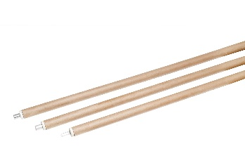
Smart submersible reinforced probe L=1000 mm SZPGU.1000
from
13 731 ₽
The smart submersible reinforced probe L=1000 mm SZPGU.1000 is designed to measure the temperature of various materials by direct contact of the probe with the measuring object and transmitting the measured value via Bluetooth to devices with the ThermoMonitor, Android program installed.
Operating conditions of the SZPGU.1000 smart probe
Ambient temperature, °C: -20...+55.
Relative humidity, %: not more than 80 at T=35 °C.
Atmospheric pressure, kPa: 86...106.
Functionality of the SZPGU.1000 smart probe
Measurement of physical quantities with a resolution of 0.01.
Recording of measured values at intervals from 5 seconds to 23 hours 59 minutes 59 seconds (only smart probes with built-in memory).
Transmitting data about measured physical quantities via Bluetooth to a device with the ThermoMonitor, Android program installed.
Transmitting information about the state of charge of the built-in battery via Bluetooth to a device with the ThermoMonitor, Android program installed.
Automatic transition to sleep mode after 50 seconds.
The ability to connect an external power supply.
Possibility of calibration.
TEKHNO-AS
Kolomna
Produced in: Kolomna, Moscow region
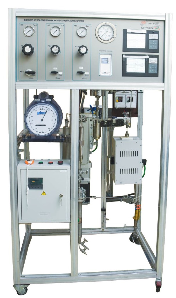
Laboratory hydrocracking/gasification unit
The laboratory unit is designed to study the catalytic and thermal processes of processing heavy petroleum raw materials.
The installation allows you to explore the following processes:
1. Hydrocracking
2. Thermal cracking
3. Gasification of water dispersions of coal, biomass, heavy oil residues.
The high-pressure liquid pump operates at temperatures up to 200°C, which makes it possible to supply high-viscosity components (fuel oil, tar, paraffin, ceresin, etc.) to the reactor.
The laboratory unit is manufactured in accordance with the technical requirements of customers so as to correspond to a wide range of technological parameters. The modular configuration of the unit allows you to change or upgrade it at any time for new tasks.
Main advantages:
1. The possibility of developing and supplying a reactor to meet customer requirements;
2. A wide range of accessories for the supply of liquids/solids;
3. Visual process control;
4. A system of control and regulation of technological parameters;
5. Convenience of loading and unloading of raw materials and reaction products;
6. The possibility of conducting long-term tests in continuous mode;
7. The possibility of upgrading the structure for new purposes;
8. Control and accurate reproduction.
YURGPU(NPI) FGBOU VO "YURGPU(NPI) IMENI M.I.PLATOVA"
Novocherkassk
Produced in: Rostov region, Novocherkassk
EVRAZTEMP Submersible thermocouples for one-time use.
Purpose: Measurement of molten metal temperature
Scope of application: Oxygen converters, electric arc furnaces, induction furnaces, blast furnaces, casting buckets
Measuring range: from 700°C to 1800°C
Accuracy: 0 + 3°C at 1554°C
Measurement time: 4 sec
Tube Length: from 100 to 1800 mm (other length is possible on request)
Slag Cap: Steel, uncapped, aluminum
Splash protection: Refractory fiber
Type of NSH: B, S, R
EVRAZPRIBOR
Lipetsk
Produced in: Lipetsk
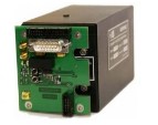
Rubidium Ch1-1014 Frequency Standard with GPS/GLONASS Signal Receiver Module
The signals of the navigation receiver's second mark and the RF available for the customer`s use are generated simultaneously on two high-frequency outputs of the receiver board. In the presence of stable reception of signals from satellites of the GLONASS and GPS radio navigation systems, the board ensures the operation of the RF in the frequency binding mode according to the signals of the second timestamp (the so-called “disciplined” rubidium frequency standard mode) with a relative error of the actual value of the RF frequency of no more than ± 5.0.10-12.
Ruknar
Nizhny Novgorod
Produced in: Nizhny Novgorod