Catalog
Search
10 products
View:
- Selected: 0Applying
- Selected: 1Names
- Selected: 0Manufacturer
- Selected: 0Made in
- Selected: 0Additional
View:
10 products

VD-3.6×1.8
A flexible waveguide is a piece of high-quality dielectric, which ends with transitions to standard waveguides with flanges.
For ease of operation, the waveguide is protected by an elastic shell.
Basic properties
Manufacturability of the connection;
Small losses and VSWR;
Economy.
Operating conditions
Operating temperature range from 5 to 50 ° C;
The relative humidity of the air is up to 98% at a temperature of 25 ° C.
Technical specifications
Waveguide cross section, mm 3.6×1.8
Flange type according to GOST RV 51914-2002
Frequency range, GHz 53.57-78.33
VSWR 1.25
Losses, 2.5 dB
Length, mm* 500
TEKHNOYAKS
Moscow
Produced in: Moscow

VD-7.2×3.4
A flexible waveguide is a piece of high-quality dielectric, which ends with transitions to standard waveguides with flanges.
For ease of operation, the waveguide is protected by an elastic shell.
Basic properties
Manufacturability of the connection;
Small losses and VSWR;
Economy.
Operating conditions
Operating temperature range from 5 to 50 ° C;
The relative humidity of the air is up to 98% at a temperature of 25 ° C.
Technical specifications
Waveguide cross section, mm 7.2×3.4
Flange type according to GOST RV 51914-2002
Frequency range, GHz 25.95-37.50
VSWR 1.25
Losses, dB 2.0
Length, mm* 500
TEKHNOYAKS
Moscow
Produced in: Moscow

FNCH-78
Structurally, waveguide LPF 37-78 GHz are made on metal plates located in the center of the E-plane of the waveguide.
These LFS can be used in conjunction with waveguide bandpass filters to increase the suppression of spurious signals and expand the upper band of the barrier.
Basic properties
Low bandwidth losses;
A wide barrage strip.
Operating conditions
Operating temperature range from minus 10
up to 50 ° C;
The relative humidity of the air is up to 98% at a temperature of 25 ° C.
Technical specifications
Waveguide cross section, mm 3.6×1.8
Bandwidth Fh-Fb at the level of -1 dB, GHz 60-78
The barrier band at the level of -30 dB, GHz 85-120
Bandwidth loss, 0.5-1.2 dB
TEKHNOYAKS
Moscow
Produced in: Moscow

FNCH-53
These LFS can be used in conjunction with waveguide bandpass filters to increase the suppression of spurious signals and expand the upper band of the barrier.
Basic properties
Low bandwidth losses;
A wide barrage strip.
Operating conditions
Operating temperature range from minus 10
up to 50 ° C;
The relative humidity of the air is up to 98% at a temperature of 25 ° C.
Technical specifications
Waveguide cross section, mm 5.2×2.6
Bandwidth Fh-Fb at the level of -1 dB, GHz 45-53.6
The barrage band at the level of -30 dB, GHz 60-78
Bandwidth loss, 0.5-1.0 dB
TEKHNOYAKS
Moscow
Produced in: Moscow
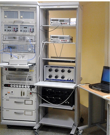
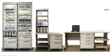
Verification module PM-10
The composition of the PM-10 verification module:
Wattmeter of passing power M2-35;
Complex transmission and reflection coefficients meter "OBZOR-804/1";
Universal voltmeter V7-81 (2 pcs.);
High-frequency signal generator G4-229;
High-frequency signal generator G4-230;
DC power supply B5-79/1 (2 pcs.);
AC power source B2-7 (2 pcs.);
The measure of DC electrical resistance is multi-valued MS3070-3, CT 0.005;
The measure of DC electrical resistance is multi-valued MS3055, CT 0.02;
Single-digit electrical resistance measures MS3080 (0.1; 1 ohm, CT 0.005);
Thermoelectric voltage converter 0.5 V;
Kit for measuring coaxial connectors KISK-7M;
PC, printer;
Basic load-bearing structures (BNC).
Technical specifications
Measuring ranges of electrical and radio engineering quantities:
Operating frequency range from 0.03 to 17.85 GHz
Passing microwave power from 0.01 to 10 MW
VSWR of the microwave tract from 1.05 to 3
Constant electrical voltage from 10 MV to 1000 V
Alternating electric voltage from 1 mV to 750 V
Thermoelectric voltage comparison from 0.1 to 0.5 V
Ranges of reproduction of electrical quantities:
Constant electrical voltage from 1 to 120 V
Resistance to direct electric current from 0.01 to 122222.21 ohms
Measurement errors of electrical and radio engineering quantities:
Passing microwave power ± (1.5 - 2.3) %
VSWR of the microwave path ± (4,15 – 10) %
Constant electrical voltage ± (0.003 – 20) %
Alternating electric voltage ± (0.09 - 15) %
Thermoelectric voltage comparison ± (0.01 – 0.1) %
Errors in the reproduction of electrical quantities:
Constant electrical voltage ± (100 – 200) mV
Resistance to direct electric current CT 0.005; 0.02
General technical characteristics:
The area occupied by the module is 4 – 8 m2
Weight, not more than 340 kg
Power supply voltage from 198 to 242 V with a frequency of (50 ± 0.5) Hz
Power consumption, not more than 2000 VA
TEKHNOYAKS
Moscow
Produced in: Moscow
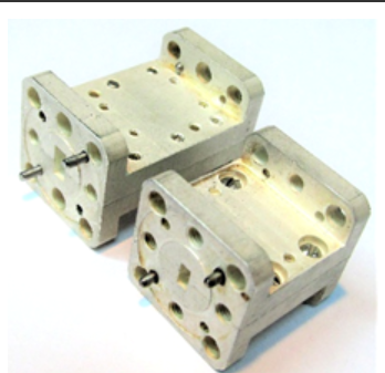
FNCH-45
Basic properties
Low bandwidth losses;
A wide barrage strip.
Operating conditions
Operating temperature range from minus 10
up to 50 ° C;
The relative humidity of the air is up to 98% at a temperature of 25 ° C.
Technical specifications
Waveguide cross section, mm 5.2×2.6
Bandwidth Fh-Fb at the level of -1 dB, GHz 37-45
The barrage band at the level of -30 dB, GHz 50-70
Bandwidth loss, 0.5-1.0 dB
TEKHNOYAKS
Moscow
Produced in: Moscow

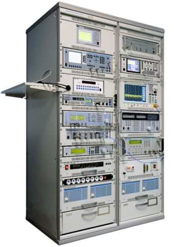
PM-8 verification module
The composition of the PM-8 verification module
Frequency comparator CHK7-1011;
Universal frequency meter Ch3-89;
AC voltage voltmeter VK3-78A;
Universal voltmeter V7-81;
AC voltage calibrator H5-5;
High-frequency signal generator G4-227;
High-frequency signal generator G4-229;
High-frequency signal generator G4-230;
Absorbed power wattmeter M3-108;
Installation for measuring attenuation D1-24/1;
Device for measuring attenuation stepwise D1-25;
Computational modulation meter SK3-49;
The meter-calibrator of the harmonic coefficient SK6-20;
Spectrum analyzer SK4-"Belan 240";
VSWR panoramic meter R2-135;
VSWR panoramic meter R2-137;
A set of exemplary measures of the transmission coefficient H3-7;
Oscilloscope S1-157/4;
DC power supply B5-79/1;
AC power source B2-7 (2 pcs.);
Electronic switch of microwave signals;
PC, printer;
Basic load-bearing structures (BNC).
Technical specifications
Measuring ranges of electrical quantities:
Constant electrical voltage from 3 MV to 1000 V
Alternating electric voltage in the frequency range of 10 Hz ... 2000 MHz from 10 mV to 100 V
Frequency of continuous electromagnetic oscillations from 0.001 Hz to 17.85 GHz
The power of continuous electromagnetic oscillations in the frequency range of 20 MHz ... 17.85 GHz from 0.8 to 10 MW
Attenuation of electromagnetic oscillations in the frequency range 0.1 MHz ... 17.85 GHz from 0 to120 dB
VSWR in the frequency range 0.2 ... 17.85 GHz from 1.03 to 2
Harmonic coefficient in the frequency range of 10 Hz ... 8 GHz from 0.005 to 100 %
The amplitude modulation coefficient in the carrier frequency range of 100 kHz ... 17.85 GHz from 0.1 to 100 %
Frequency deviation in the carrier frequency range of 100 kHz ... 17.85 GHz from 5 Hz to 1 MHz
Phase modulation index in the carrier frequency range 100 kHz ... 17.85 GHz from 1 to 100 radians
Phase shift between two harmonic signals in the frequency range 0.1 MHz ... 17.85 GHz from 0 to 360o
Ranges of reproduction of electrical quantities:
Alternating electrical voltage in the frequency range of 10 Hz ... 2000 MHz from 3 MV to 3 V
Harmonic (sinusoidal) signal at a load of 50 ohms in the frequency range of 0.001 Hz ... 30 MHz from 0.01 to 5 V
Continuous electromagnetic oscillations in the frequency range of 9 kHz ... 17.85 GHz from minus 120 to 13 dBm
5 and 10 MHz reference frequency signal
Attenuation of electromagnetic oscillations in the frequency range 0 ... 3 GHz from 0 to 86 dB
Measurement errors of electrical quantities:
Constant electrical voltage ± (0.0025 ... 16.7) %
Alternating electric voltage in the frequency range 10 Hz ... 2000 MHz ± (0.2 ... 16) %
Frequency of continuous electromagnetic oscillations ± (2·10-7 ... 4·10-3)
Power of continuous electromagnetic oscillations in the frequency range 20 MHz ... 17.85 GHz ± (4 ... 6) %
Attenuation of electromagnetic oscillations in the frequency range 0.1 MHz ... 17.85 GHz ± (0.01 ... 1.2) dB
VSWR in the frequency range 0.2 ... 17.85 GHz ± (3 ... 5) K
Harmonic coefficient in the frequency range 10 Hz ... 8 GHz ± (0.005 ... 6) %
Amplitude modulation coefficient in the carrier frequency range 100 kHz ... 17.85 GHz ± (0.1 ... 9) %
Frequency deviation in the carrier frequency range 100 kHz ... 17.85 GHz ± (0.2 ... 80) Hz
Phase modulation index in the carrier frequency range 100 kHz ... 17.85 GHz ± (0.02 ... 5) radians
Phase shift between two harmonic signals in the frequency range 0.1 MHz ... 17.85 GHz ± (0.01 ... 0.08) o
Errors in the reproduction of electrical quantities:
Alternating electrical voltage in the frequency range 10 Hz ... 2000 MHz ± (0.16 ... 10) %
Harmonic (sinusoidal) signal at a load of 50 ohms in the frequency range 0.001 Hz ... 30 MHz ± (3 ... 5) %;
Continuous electromagnetic oscillations in the frequency range of 9 kHz ... 17.85 GHz ± (0.5 ... 3) dB
5 and 10 MHz reference frequency signal ± (2·10-11 – 2,4·10-10)
Attenuation of electromagnetic oscillations in the frequency range 0 ... 3 GHz ± (0.2 ... 1.4) dB
General technical characteristics:
The area occupied by the module is 6-12 m2
Weight, not more than 550 kg
Power supply voltage from 198 to 242 V with a frequency of (50 ± 0.5) Hz
Power consumption, no more than 3000 VA
TEKHNOYAKS
Moscow
Produced in: Moscow
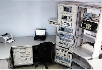
Verification module PM-9
The composition of the PM-9 calibration module:
Universal voltmeter calibrator H4-12 (2 pcs.);
Variable voltage calibrator H5-5A;
A measure of the stress ratio H4-8;
AC voltage voltmeter VK3-78A;
Generator-calibrator of harmonic signals SK6-122;
The meter-calibrator of the harmonic coefficient SK6-20A;
AC power source B2-7 (2 pcs.);
The measure of DC electrical resistance is multi-valued MS3070-2;
The measure of DC electrical resistance is multi-valued MS3055;
Decadal high-resistance resistance magazine M-109R;
Single-digit electrical resistance measures MS3080 (0.001; 0.01; 0.1 ohms);
Electrical resistance measures unambiguous MS3050M (1, 10, 100, 1000, 10000, 100000 Om);
The measure of electrical resistance is unambiguous P4013;
The measure of electrical resistance is unambiguous P4023;
The measure of electrical resistance is unambiguous P4033;
PC, printer;
Basic load-bearing structures (BNC).
Technical specifications
Measuring ranges of electrical quantities:
Constant electrical voltage DC from 1 MV to 1000 V
AC alternating electric voltage in the frequency range of 10 Hz ... 1 MHz from 10 mV to 1000 V
Alternating electric voltage high-frequency VRF in the frequency range of 10 Hz ... 2000 MHz from 10 mV to 100 V
Harmonic coefficient in the frequency range of 10 Hz ... 200 kHz from 0.001 to 100 %
Ranges of reproduction of electrical quantities:
Constant electrical voltage DC from 1 nV to 1000 V
AC alternating electric voltage in the frequency range of 10 Hz ... 1 MHz from 3 MV to 1000 V
Alternating electric voltage high-frequency VRF in the frequency range of 1 MHz ... 2000 MHz from 3 MV to 3 V
DC electric current from 1 µA to 20 A
The power of alternating electric current in the frequency range from 0.1 Hz to 10 kHz from 1 µA to 20 A
Electrical resistance from 0.001 ohms to 11
ohms Harmonic coefficient in the frequency range from 10 Hz to 200 kHz from 0.001 to 100 %
Measurement errors of electrical quantities:
Constant electrical voltage DC ± (0.0011 ... 4.0) %
AC alternating electric voltage, in the frequency range 10 Hz ... 1 MHz ± (0.0055 ... 1.2) %
Alternating electric voltage high-frequency VRF in the frequency range 1 MHz ... 2000 MHz ± (0.2 ... 6.0) %
Harmonic coefficient in the frequency range from 10 Hz to 200 kHz ± (0.0008 ... 2.0) %
Errors in the reproduction of electrical quantities:
Constant electrical voltage DC ± (0.0011 ... 4.0) %
AC alternating electric voltage in the frequency range 10 Hz ... 1 MHz ± (0.0055 ... 4.0) %
Alternating electric voltage high-frequency VRF in the frequency range 1 MHz ... 2000 MHz ± (0.6 ... 10.0) %
DC power ± (0.0033 ... 0.5) %
The power of alternating electric current in the frequency range from 10 Hz to 10 kHz ± (0.055 ... 1.0) %
Electrical resistance ± (0.001 ... 1.0) %
Harmonic coefficient in the frequency range from 10 Hz to 200 kHz ± (0.006 ... 2.0) %
General technical characteristics:
The area occupied by the module is 6-12 m2
Weight, not more than 430 kg
Power supply voltage from 198 to 242 V with a frequency of (50 ± 0.5) Hz
Power consumption, no more than 2000 VA
TEKHNOYAKS
Moscow
Produced in: Moscow
Verification module PM-3
The composition of the PM-3 verification module:
Frequency comparator CHK7-1011;
Universal frequency meter Ch3-86A;
Universal voltmeter V7-79;
Absorbed power wattmeter M3-108-2;
High-frequency signal generator G4-229;
High-frequency signal generator G4-230;
Generator of test pulses G9-1A;
Oscilloscope S1-177;
DC power supply B5-79/1;
Electronic switchboard of RF signals;
AC power source B2-7 (2 pcs.);
PC, printer;
Basic load-bearing structures (BNC).
Technical specifications
Measurement ranges of time-frequency parameters of signals:
Continuous oscillation frequency from 0.005 Hz to 17.85 GHz
Pulse repetition rate from 0.01 Hz to 100 MHz
The carrier frequency of the IM signal is from 100 MHz to 17.85 GHz
Pulse duration from 10 ns to 1000 s
Time interval from 0 to 1000 s
Nominal values of the frequency of the studied signals are 2,048; 5,0; 10,0; 10,24 MHz
Measurement errors of time-frequency parameters of signals:
Frequency of continuous oscillations ± (2,4·10-10 - 4·10-3)
Pulse repetition rate ± (2·10-7 - 2·10-3)
The carrier frequency of the IM signal is ± 2·10-7
Pulse duration ± (1 - 200) ns
Time interval ± (1 - 200) ns
The relative deviation of the frequency of the studied signal from the reference frequency ± (5·10-13 - 2·10-12)
Frequency of continuous oscillations ± (3·10-11 – 1,1·10-5)
Pulse repetition rate ± (2·10-11 – 6·10-5)
Carrier frequency of the IM signal ± (3·10-11 – 1,1·10-5)
Pulse duration ± (1·10-8 – 7,2·10-4)
Time interval ± (2·10-10 – 7,2·10-4)
Nominal values of the reference signal frequency ± (2·10-11 – 2,4·10-10)
General technical characteristics:
The area occupied by the module is 8-12 m2
Weight, not more than 327 kg
Power supply voltage from 198 to 242 V frequency (50 ± 0.5) Hz
Power consumption, no more than 2400 VA
TEKHNOYAKS
Moscow
Produced in: Moscow