All categories
Clear
Search in item titles
Sorting
Cancel
Item name
Item description
Item name and description
Company name
Submit
Search
Cancel
Submit
Equipment
Furniture
Accessories
Reagent
Metrology
Consumables
Glassware
Игра
Plastic
Glass
Porcelain
Personal Account
Language selection
Cancel
English
en
Русский
ru
Français
fr
Español
es
عرب
ar
فارْسِى
fa
中國
cn
Catalog
Equipment
Reagent
Custom work
Custom work
NASHA LABA.BIOTECH
Furniture
Home
News
About
Volunteers
Help
Contacts
NASHA LABA possibilities
Catalog
Reagents register
Custom work
Custom work
Проект «У нас есть такие приборы»
Scientific Equipment Repair
НАША ЛАБА.ВИНО
Equipment
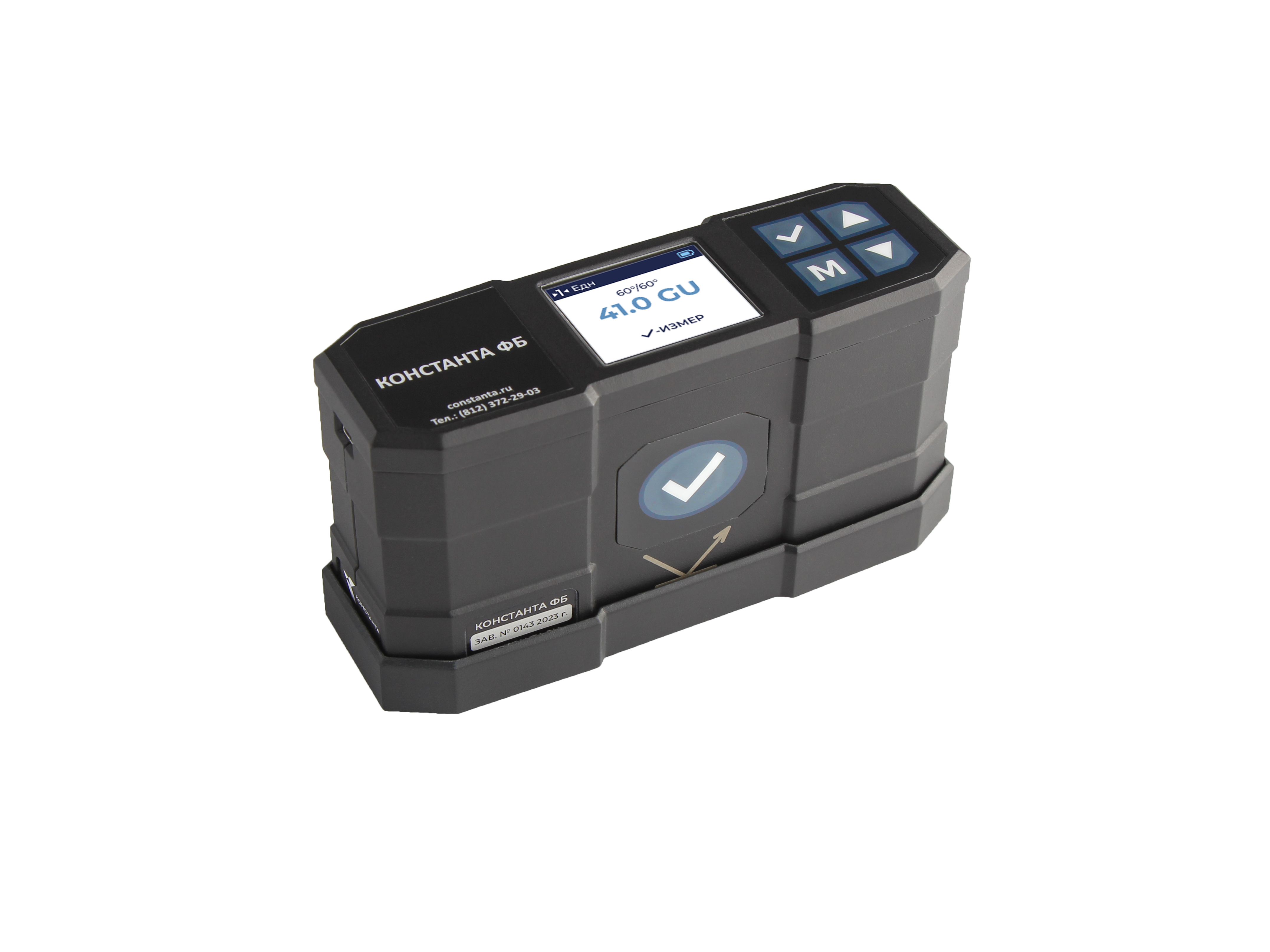
Блескомер Константа ФБ 20°/20°, 60°/60°, 85°/85°
from
285060.00
KONSTANTA
Saint Petersburg
Product of the day
Registration
Seller
Manufacturer
Buyer
User
Home
Catalog
Equipment
Equipment
2221 products
View:
Areas of use
Selected: 0
24
Reset 0 of 24
Areas of use
Agriculture
biology
chemical analysis
chemistry
criminalistics
electrical engineering
electrical measuring equipment
electrochemistry
electronics
engineering
general laboratory
geodesy
geology
geophysics
Materials Science
measuring equipment (except for electro- and chemistry)
Loading...
Item names
Selected: 0
387
Reset 0 of 387
Item names
AC source
acid-resistant fan
actinometric rack
ADC
adsorption dryer
air generator
air ion counter
air ion generator
aluminum melting furnace
amplifier
analyzer
anemometer
anemometer remote control
antenna
apparatus for determining the content of total sediment
apparatus for determining the fractional composition of oil
Loading...
Manufacturer
Selected: 0
125
Reset 0 of 125
Manufacturer
"FIANUM LAB"
Abisens
ADVIN Smart Faktory
AGM SISTEMY
Aivok
Astra Lab
Atomtekh
AZPT LTD
BELAKVILON
Biotekhno
BIVER TEKH
Burevestnik
CHIMLABORPRIBOR
Department of Analytical Instrumentation SFU
Diamekh
DIPAUL
Loading...
Made in
Selected: 0
57
Reset 0 of 57
Made in
Aramil
Balashikha
Belarus
Belgorod
Bryansk
Bryansk region
Chernogolovka
Crimea
Dolgoprudny
Dzerzhinsk
Ekaterinburg
Feodosia
Ivanovo
Ivanteevka
Kaluga region
Kazan
Loading...
Additional
Selected: 0
99
Reset 0 of 99
Additional
acoustics
analytic_chemistry
ASM
Atom stations
atomic absorption
atomic emission
bend
biohazard
biosecurity
burning
catalysis
chromass
chromatography
cleaning
coking
compression
Loading...
All filters
All filters
Areas of use
Selected: 0
24
Reset 0 of 24
Areas of use
Agriculture
biology
chemical analysis
chemistry
criminalistics
electrical engineering
electrical measuring equipment
electrochemistry
electronics
engineering
general laboratory
geodesy
geology
geophysics
Materials Science
measuring equipment (except for electro- and chemistry)
Loading...
Item names
Selected: 0
387
Reset 0 of 387
Item names
AC source
acid-resistant fan
actinometric rack
ADC
adsorption dryer
air generator
air ion counter
air ion generator
aluminum melting furnace
amplifier
analyzer
anemometer
anemometer remote control
antenna
apparatus for determining the content of total sediment
apparatus for determining the fractional composition of oil
Loading...
Manufacturer
Selected: 0
125
Reset 0 of 125
Manufacturer
"FIANUM LAB"
Abisens
ADVIN Smart Faktory
AGM SISTEMY
Aivok
Astra Lab
Atomtekh
AZPT LTD
BELAKVILON
Biotekhno
BIVER TEKH
Burevestnik
CHIMLABORPRIBOR
Department of Analytical Instrumentation SFU
Diamekh
DIPAUL
Loading...
Made in
Selected: 0
57
Reset 0 of 57
Made in
Aramil
Balashikha
Belarus
Belgorod
Bryansk
Bryansk region
Chernogolovka
Crimea
Dolgoprudny
Dzerzhinsk
Ekaterinburg
Feodosia
Ivanovo
Ivanteevka
Kaluga region
Kazan
Loading...
Additional
Selected: 0
99
Reset 0 of 99
Additional
acoustics
analytic_chemistry
ASM
Atom stations
atomic absorption
atomic emission
bend
biohazard
biosecurity
burning
catalysis
chromass
chromatography
cleaning
coking
compression
Loading...
Areas of use
Selected: 0
24
Reset 0 of 24
Areas of use
Agriculture
biology
chemical analysis
chemistry
criminalistics
electrical engineering
electrical measuring equipment
electrochemistry
electronics
engineering
general laboratory
geodesy
geology
geophysics
Materials Science
measuring equipment (except for electro- and chemistry)
Loading...
Item names
Selected: 0
387
Reset 0 of 387
Item names
AC source
acid-resistant fan
actinometric rack
ADC
adsorption dryer
air generator
air ion counter
air ion generator
aluminum melting furnace
amplifier
analyzer
anemometer
anemometer remote control
antenna
apparatus for determining the content of total sediment
apparatus for determining the fractional composition of oil
Loading...
Manufacturer
Selected: 0
125
Reset 0 of 125
Manufacturer
"FIANUM LAB"
Abisens
ADVIN Smart Faktory
AGM SISTEMY
Aivok
Astra Lab
Atomtekh
AZPT LTD
BELAKVILON
Biotekhno
BIVER TEKH
Burevestnik
CHIMLABORPRIBOR
Department of Analytical Instrumentation SFU
Diamekh
DIPAUL
Loading...
Made in
Selected: 0
57
Reset 0 of 57
Made in
Aramil
Balashikha
Belarus
Belgorod
Bryansk
Bryansk region
Chernogolovka
Crimea
Dolgoprudny
Dzerzhinsk
Ekaterinburg
Feodosia
Ivanovo
Ivanteevka
Kaluga region
Kazan
Loading...
Additional
Selected: 0
99
Reset 0 of 99
Additional
acoustics
analytic_chemistry
ASM
Atom stations
atomic absorption
atomic emission
bend
biohazard
biosecurity
burning
catalysis
chromass
chromatography
cleaning
coking
compression
Loading...
View:
Фильтр
2221 products
1
...
183
184
185
186
Show on page:
12
24
36
Home
Catalog
Search
Personal Account
Lang