Catalog

TEKHNOYAKS
61 products
View:
Telephone number:
E-mail:
mail@tehnojaks.ru
Website: https://tehnojaks.com
Address:
Russia, Moscow, 30
Website: https://tehnojaks.com
Address:
Russia, Moscow, 30
- Selected: 0Areas of use
- Selected: 0Item names
- Selected: 0Manufacturer
- Selected: 0Made in
- Selected: 0Additional
View:
51 products
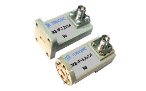
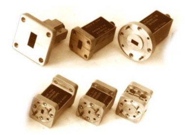
PKV-IB-7,2×3,4
Basic properties
Wide frequency range;
Small VSWR values.
Operating conditions
Operating temperature range from minus 10 to 50 ° C;
The relative humidity of the air is up to 98% at a temperature of 25 ° C.
Technical specifications
Waveguide cross section, mm 7.2×3.4
Type of coaxial connector (according to GOST RV 51914-2002) IB
Frequency range, GHz 25.96-37.50
VSWR 1.35
TEKHNOYAKS
Moscow
Produced in: Moscow

PKV-IP-5,2×2,6
Basic properties
Wide frequency range;
Small VSWR values.
Operating conditions
Operating temperature range from minus 10 to 50 ° C;
The relative humidity of the air is up to 98% at a temperature of 25 ° C.
Technical specifications
Waveguide cross section, mm 5.2×2.6
Type of coaxial connector (according to GOST RV 51914-2002) IP
Frequency range, GHz 37.50-50.00
VSWR 1.45
TEKHNOYAKS
Moscow
Produced in: Moscow

VD-3.6×1.8
A flexible waveguide is a piece of high-quality dielectric, which ends with transitions to standard waveguides with flanges.
For ease of operation, the waveguide is protected by an elastic shell.
Basic properties
Manufacturability of the connection;
Small losses and VSWR;
Economy.
Operating conditions
Operating temperature range from 5 to 50 ° C;
The relative humidity of the air is up to 98% at a temperature of 25 ° C.
Technical specifications
Waveguide cross section, mm 3.6×1.8
Flange type according to GOST RV 51914-2002
Frequency range, GHz 53.57-78.33
VSWR 1.25
Losses, 2.5 dB
Length, mm* 500
TEKHNOYAKS
Moscow
Produced in: Moscow
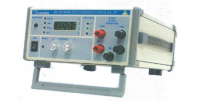
DC power supply B5-79
The B5-79 DC power supply is designed to provide constant voltage and current to measuring instruments and equipment during the development, production, operation and repair of electronic devices.
Technical specifications
Output voltage setting range from 0 to 60 V
Output current setting range from 0.2 to 10 A
Maximum output power 300W
The main error of the output voltage setting is ± 300 mV
The main error of the output current setting is ± 100 mA
Additional error in setting the output voltage caused by a deviation of the mains voltage from the nominal value by ± 10% ± (0.0001 · Uust + 1 mV)
Additional error in setting the output voltage caused by a change in the load current from 0.9 of the maximum value to zero ± (0.0002 · Uust + 5 mV)
Additional error in setting the output current caused by a deviation of the mains voltage from the nominal value by ± 10% ± (0.0002 · Iust + 2 mA)
Additional error in setting the output current caused by a change in the load voltage from 0.9 of the maximum value to zero ± (0.0005 · Iust + 5 mA)
Instability of the output voltage for any 10 minutes during 8 hours of continuous operation, no more than ± 50 mV
Instability of the output current for any 10 minutes during 8 hours of continuous operation, no more than ± 50 mA
Operating temperature range from minus 10 to 50 °C
AC power supply 220 V, 50 Hz
Power consumption, no more than 500 VA
Overall dimensions, mm 240x128x313
Weight, not more than 6.0 kg
TEKHNOYAKS
Moscow
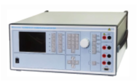
Universal calibrator H4-20A
The calibrator is capable of operating both independently and as part of automated measuring systems with interfaces such as RS-232 and ETHERNET.
Technical specifications
Ranges of reproduction of quantities:
- constant electrical voltage from 500 MV to 1000 V
- alternating electric voltage in the frequency range from 40 Hz to 2.5 kHz from 1 mV to 1000 V
- the power of direct electric current from 10 µA to 50 A
- the power of alternating electric current in the frequency range from 40 Hz to 2.5 kHz from 100 µA to 50 A
- frequency of alternating electric voltage from 40 Hz to 2.5 kHz
Errors in reproducing quantities:
- constant electric voltage ± (0.02 – 2.4)%
- alternating electric voltage in the frequency range from 40 Hz to 2.5 kHz ± (0.03 – 2.1)%
- constant electric current ± (0.03 – 0.25)%
- alternating electric current in the frequency range from 40 Hz to 2.5 kHz ± (0.04 -0.25)%
- frequency of alternating electric voltage ± 0.02%
The value of the phase shift between voltage and current with simultaneous ignition ± 2 °
General characteristics:
Operating temperature range from 5 to 40 °C
AC power supply 220 V, 50 Hz
Power consumption, no more than 1000 VA
Overall dimensions, mm 455x198x463
Weight, not more than 20 kg
TEKHNOYAKS
Moscow
Produced in: Moscow
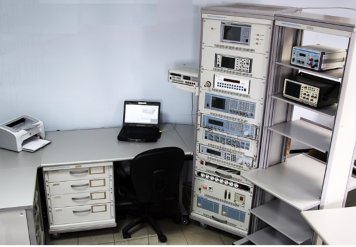
Verification module PM-3
The composition of the PM-3 verification module:
Frequency comparator CHK7-1011;
Universal frequency meter Ch3-86A;
Universal voltmeter V7-79;
Absorbed power wattmeter M3-108-2;
High-frequency signal generator G4-229;
High-frequency signal generator G4-230;
Generator of test pulses G9-1A;
Oscilloscope S1-177;
DC power supply B5-79/1;
Electronic switchboard of RF signals;
AC power source B2-7 (2 pcs.);
PC, printer;
Basic load-bearing structures (BNC).
Technical specifications
Measurement ranges of time-frequency parameters of signals:
Continuous oscillation frequency from 0.005 Hz to 17.85 GHz
Pulse repetition rate from 0.01 Hz to 100 MHz
The carrier frequency of the IM signal is from 100 MHz to 17.85 GHz
Pulse duration from 10 ns to 1000 s
Time interval from 0 to 1000 s
Nominal values of the frequency of the studied signals are 2,048; 5,0; 10,0; 10,24 MHz
Measurement errors of time-frequency parameters of signals:
Frequency of continuous oscillations ± (2,4·10-10 - 4·10-3)
Pulse repetition rate ± (2·10-7 - 2·10-3)
The carrier frequency of the IM signal is ± 2·10-7
Pulse duration ± (1 - 200) ns
Time interval ± (1 - 200) ns
The relative deviation of the frequency of the studied signal from the reference frequency ± (5·10-13 - 2·10-12)
Frequency of continuous oscillations ± (3·10-11 – 1,1·10-5)
Pulse repetition rate ± (2·10-11 – 6·10-5)
Carrier frequency of the IM signal ± (3·10-11 – 1,1·10-5)
Pulse duration ± (1·10-8 – 7,2·10-4)
Time interval ± (2·10-10 – 7,2·10-4)
Nominal values of the reference signal frequency ± (2·10-11 – 2,4·10-10)
General technical characteristics:
The area occupied by the module is 8-12 m2
Weight, not more than 327 kg
Power supply voltage from 198 to 242 V frequency (50 ± 0.5) Hz
Power consumption, no more than 2400 VA
TEKHNOYAKS
Moscow
Produced in: Moscow
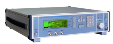
High-frequency signal generator G4-227
The generator is capable of operating both independently and as part of automated measuring systems with USB and IEEE-488 (CPC) interfaces.
Technical specifications
Frequency range from 9 kHz to 6 GHz
Frequency tuning discreteness of 1 Hz
The main error of the frequency setting is ± 3x10⁻⁷ Hz
The range of setting the output signal power level at the main output is from minus 10 to 13 dBm
The basic error of setting the reference power level is ± (0.5 – 1.0) dB
Instability of the output signal power level for any 15-minute time interval of no more than 0.1 dB
Metrological characteristics of the generator in the FM operation mode:
- frequency range of the modulating signal from 1 to 100 kHz
- frequency deviation setting range (taking into account the carrier frequency value) from 12.5 to 4000 kHz
- the main error of the frequency deviation setting is ± (20 – 25)%
Metrological characteristics of the generator in AM operation mode:
- frequency range of the modulating signal from 0.05 to 5.0 kHz
- the range of setting the amplitude modulation coefficient from 1 to 100 %
- the basic error of setting the amplitude modulation coefficient ± (0.25 M + 0.2)%
Metrological characteristics of the generator in the IM operation mode:
- the duration range of modulating pulses from 300 ns to 20 s
- the range of the modulating pulse repetition period from 340 ns to 30 s
- the difference in the duration of the output RF pulses from the duration of the modulating pulses ± 200 ns
Operating temperature range from minus 10 to 40 °C
AC power supply 220 V, 50 Hz
Power consumption, not more than 100 VA
Overall dimensions, mm 498x136x487
Weight, not more than 13 kg
TEKHNOYAKS
Moscow
Produced in: Moscow
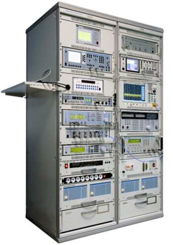
PM-8 verification module
The composition of the PM-8 verification module
Frequency comparator CHK7-1011;
Universal frequency meter Ch3-89;
AC voltage voltmeter VK3-78A;
Universal voltmeter V7-81;
AC voltage calibrator H5-5;
High-frequency signal generator G4-227;
High-frequency signal generator G4-229;
High-frequency signal generator G4-230;
Absorbed power wattmeter M3-108;
Installation for measuring attenuation D1-24/1;
Device for measuring attenuation stepwise D1-25;
Computational modulation meter SK3-49;
The meter-calibrator of the harmonic coefficient SK6-20;
Spectrum analyzer SK4-"Belan 240";
VSWR panoramic meter R2-135;
VSWR panoramic meter R2-137;
A set of exemplary measures of the transmission coefficient H3-7;
Oscilloscope S1-157/4;
DC power supply B5-79/1;
AC power source B2-7 (2 pcs.);
Electronic switch of microwave signals;
PC, printer;
Basic load-bearing structures (BNC).
Technical specifications
Measuring ranges of electrical quantities:
Constant electrical voltage from 3 MV to 1000 V
Alternating electric voltage in the frequency range of 10 Hz ... 2000 MHz from 10 mV to 100 V
Frequency of continuous electromagnetic oscillations from 0.001 Hz to 17.85 GHz
The power of continuous electromagnetic oscillations in the frequency range of 20 MHz ... 17.85 GHz from 0.8 to 10 MW
Attenuation of electromagnetic oscillations in the frequency range 0.1 MHz ... 17.85 GHz from 0 to120 dB
VSWR in the frequency range 0.2 ... 17.85 GHz from 1.03 to 2
Harmonic coefficient in the frequency range of 10 Hz ... 8 GHz from 0.005 to 100 %
The amplitude modulation coefficient in the carrier frequency range of 100 kHz ... 17.85 GHz from 0.1 to 100 %
Frequency deviation in the carrier frequency range of 100 kHz ... 17.85 GHz from 5 Hz to 1 MHz
Phase modulation index in the carrier frequency range 100 kHz ... 17.85 GHz from 1 to 100 radians
Phase shift between two harmonic signals in the frequency range 0.1 MHz ... 17.85 GHz from 0 to 360o
Ranges of reproduction of electrical quantities:
Alternating electrical voltage in the frequency range of 10 Hz ... 2000 MHz from 3 MV to 3 V
Harmonic (sinusoidal) signal at a load of 50 ohms in the frequency range of 0.001 Hz ... 30 MHz from 0.01 to 5 V
Continuous electromagnetic oscillations in the frequency range of 9 kHz ... 17.85 GHz from minus 120 to 13 dBm
5 and 10 MHz reference frequency signal
Attenuation of electromagnetic oscillations in the frequency range 0 ... 3 GHz from 0 to 86 dB
Measurement errors of electrical quantities:
Constant electrical voltage ± (0.0025 ... 16.7) %
Alternating electric voltage in the frequency range 10 Hz ... 2000 MHz ± (0.2 ... 16) %
Frequency of continuous electromagnetic oscillations ± (2·10-7 ... 4·10-3)
Power of continuous electromagnetic oscillations in the frequency range 20 MHz ... 17.85 GHz ± (4 ... 6) %
Attenuation of electromagnetic oscillations in the frequency range 0.1 MHz ... 17.85 GHz ± (0.01 ... 1.2) dB
VSWR in the frequency range 0.2 ... 17.85 GHz ± (3 ... 5) K
Harmonic coefficient in the frequency range 10 Hz ... 8 GHz ± (0.005 ... 6) %
Amplitude modulation coefficient in the carrier frequency range 100 kHz ... 17.85 GHz ± (0.1 ... 9) %
Frequency deviation in the carrier frequency range 100 kHz ... 17.85 GHz ± (0.2 ... 80) Hz
Phase modulation index in the carrier frequency range 100 kHz ... 17.85 GHz ± (0.02 ... 5) radians
Phase shift between two harmonic signals in the frequency range 0.1 MHz ... 17.85 GHz ± (0.01 ... 0.08) o
Errors in the reproduction of electrical quantities:
Alternating electrical voltage in the frequency range 10 Hz ... 2000 MHz ± (0.16 ... 10) %
Harmonic (sinusoidal) signal at a load of 50 ohms in the frequency range 0.001 Hz ... 30 MHz ± (3 ... 5) %;
Continuous electromagnetic oscillations in the frequency range of 9 kHz ... 17.85 GHz ± (0.5 ... 3) dB
5 and 10 MHz reference frequency signal ± (2·10-11 – 2,4·10-10)
Attenuation of electromagnetic oscillations in the frequency range 0 ... 3 GHz ± (0.2 ... 1.4) dB
General technical characteristics:
The area occupied by the module is 6-12 m2
Weight, not more than 550 kg
Power supply voltage from 198 to 242 V with a frequency of (50 ± 0.5) Hz
Power consumption, no more than 3000 VA
TEKHNOYAKS
Moscow
Produced in: Moscow
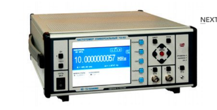
Universal frequency meter Ch3-92
The frequency meter is able to work both independently and as part of automated measuring systems with interfaces such as USB or RS-232.
Technical specifications
Frequency and period of sinusoidal signals (inputs A, B) 0.001 Hz - 300 MHz
Frequency and period of video pulse signals (inputs A, B) 0.001 Hz - 300 MHz
Frequency of continuous sinusoidal oscillations (input C) (0.3 – 37.5) GHz
Pulse duration 10 ns - 1000 s
The duration of the front, the decay of the pulses is 5 ns - 100 microseconds
Time interval from -1000 to 1000 s
Frequency measurement resolution 2x10⁻¹⁰ s/Rng
The range of setting the trigger levels (inputs A, B) from minus 2.5 to 2.5 V
The error of setting the trigger levels (inputs A, B) ± 0.05 V
Input signal level:
• for sinusoidal signal (inputs A, B) (0.03 - 10.0) V
• for video pulse signal (inputs A, B) (0.1 - 10.0) V
• for sinusoidal signal (input C) 50 MW - 5 MW
Input resistance
• Inputs A, B (50±2.5) ohms; (1±0.1) MOm/100 pF
• Input With (50±2.5) ohms
Nominal frequency value of the reference quartz oscillator 10 MHz
Relative error in the frequency of the quartz oscillator, no more than ± 2x10⁻⁷ in 12 months
Operating temperature range from minus 10 to 40 °C
AC power supply 220 V, 50 Hz
Power consumption, not more than 100 VA
Overall dimensions, mm
299x136x436,5
Weight, not more than 8.5 kg
TEKHNOYAKS
Moscow
Produced in: Moscow
UCHX2-78
Basic properties:
Wide frequency range;
Sufficiently large output power;
High level of suppression of side harmonics of the input signal;
Low phase noise value;
Relatively simple technical solutions:
- synchronization and frequency stabilization,
- stabilization and adjustment of the output power level,
- implementation of amplitude and frequency modulation modes;
Do not require external bias diodes.
Operating conditions:
Operating temperature range from minus 10 to 50 ° C;
The relative humidity of the air is up to 98% at a temperature of 25 ° C.
Technical characteristics
Input/output frequency range, GHz 26,78-39,17 / 53,57-78,33
Losses (max.), dB 15
Input power level, dBm 15-21
Unevenness of output power (Rvh. = 20 dBm), dB ± 2.0
The level of parasitic harmonics of the input signal at the output (min.), dBn 20
Output VSWR (max.) 2.0
Connector type:
• Input Coax. 2.4/1.0 mm (plug/socket)
• Output Waveguide 3,759x1,88 mm (50-75GGo)
Overall dimensions, mm 26x20x20
Weight, g 50
TEKHNOYAKS
Moscow
Produced in: Moscow
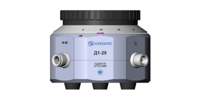
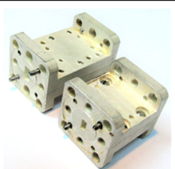
Measuring step attenuator D1-29
The device replaces the devices for checking the attenuators D1-13A and D1-25.
D1-29 is a step attenuator with a range of attenuation from 0 to 110 dB with a step of 10 dB, operating in the frequency range from 0 to 150 MHz.
The device consists of a housing with damping cells and a switch with a counting device. The housing contains coaxial input and output connectors, as well as additional connectors "40 dB" and "80 dB", necessary for the verification of the device.
Technical specifications
Operating frequency range 0 – 150 MHz
Difference attenuation setting range (after 10 dB) 0 – 110 dB
Input electrical resistance to direct current 50 ± 0.1 ohms
The output electrical resistance to direct current when connected to the load input is 50 ± 0.1 ohms 25 ± 0.1 ohms
The main absolute error of the difference attenuation setting relative to the 0 dB mark at direct current ± (0.002 - 0.02) dB
The main absolute error of the difference attenuation setting relative to the 10 dB mark in the frequency range up to 30 MHz ± (0.004 - 0.9) dB
The main absolute error of the difference attenuation setting relative to the 10 dB mark in the frequency range over 30 to 150 MHz ± (0.09 - 3.0) dB
The maximum permissible value of the electrical voltage (DC or AC) at the input of the attenuator 3 In
the operating temperature range from 5 to 40 ° C
Overall dimensions, mm 149x95x149
Weight, not more than 3 kg
TEKHNOYAKS
Moscow
Produced in: Moscow