Catalog
Search
619 products
View:
- Selected: 1Areas of use
- Selected: 0Item names
- Selected: 0Manufacturer
- Selected: 0Made in
- Selected: 0Additional
View:
619 products
AF011B Microassembly
A high-speed signal limiter amplifier.
Designed for use in electronic counting frequency meters.
Description:
The magnitude of the input signals for selecting the switch input and inverting the signal of the limiter amplifier at a supply voltage of ± 5 V:
- logical "0"
not more than 0.2 V;
- logical "1"
at least 4.8 V.
The value of the input signals of switching on / off the switch at a supply voltage of ± 5 V:
- logical "0"
no more than 3.3 V;
- logical "1"
at least 4.1 V.
The magnitude of the output signals of the switch at a supply voltage of ± 5 V and a load of 300 ohms connected to zero potential:
- logical "0"
from 3.1 V to 3.4 V;
- logical "1"
from 4.0 V to 4.3 V.
The minimum input voltage of the sinusoidal shape in the frequency range from 10 Hz to 200 MHz should be no more than 30 mV.
The maximum input voltage of the sinusoidal shape in the frequency range from 10 Hz to 200 MHz must be at least 1 V.
The value of the supply voltage:
- positive
5±0.2 V;
- negative
-5±0.2 V.
The current consumption should be no more than:
- from a positive power source
110 mA;
- from a negative power supply
35 mA.
MNIPI
Minsk
Produced in: Belarus, Minsk
DOSIMETRIC INSTALLATION OF GAMMA RADIATION UDG‑AT110
Irradiator with a typical collimator
Rotary drum magazine sources in tungsten and lead protection
Software control of the movement of sources and positioning of the mobile platform
An alarm and blocking system, radiation monitoring system to ensure the safety of the installation
Control from the operator panel or computer with verification automation functions
Atomtekh
Minsk
Produced in: Belarus, Minsk
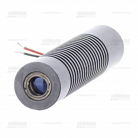
Green Laser Module KLM-A532-5-5 532nm 5mW dot
from
13 184 ₽
KLM-A532-5-5 laser modules are optimal sources of coherent radiation for the construction of control and automation systems, alignment and marking devices, for scientific and medical purposes.
FTI-Optronik
Saint Petersburg
Produced in: Saint Petersburg
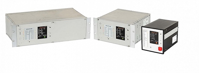
RELAY PROTECTION UNITS FOR DIGITAL SUBSTATION OF THE IED-EP+ SERIES
A series of modern intelligent relay protection, automation and alarm units PARMA IED-EP+ is designed for use in networks with a voltage from 6 to 750 kV
PARMA
Saint Petersburg
Produced in: Saint Petersburg
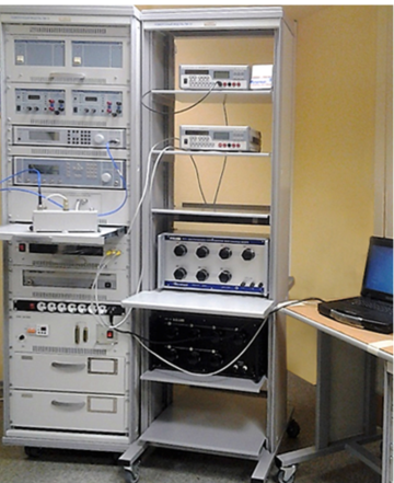
Verification module PM-10
The composition of the PM-10 verification module:
Wattmeter of passing power M2-35;
Complex transmission and reflection coefficients meter "OBZOR-804/1";
Universal voltmeter V7-81 (2 pcs.);
High-frequency signal generator G4-229;
High-frequency signal generator G4-230;
DC power supply B5-79/1 (2 pcs.);
AC power source B2-7 (2 pcs.);
The measure of DC electrical resistance is multi-valued MS3070-3, CT 0.005;
The measure of DC electrical resistance is multi-valued MS3055, CT 0.02;
Single-digit electrical resistance measures MS3080 (0.1; 1 ohm, CT 0.005);
Thermoelectric voltage converter 0.5 V;
Kit for measuring coaxial connectors KISK-7M;
PC, printer;
Basic load-bearing structures (BNC).
Technical specifications
Measuring ranges of electrical and radio engineering quantities:
Operating frequency range from 0.03 to 17.85 GHz
Passing microwave power from 0.01 to 10 MW
VSWR of the microwave tract from 1.05 to 3
Constant electrical voltage from 10 MV to 1000 V
Alternating electric voltage from 1 mV to 750 V
Thermoelectric voltage comparison from 0.1 to 0.5 V
Ranges of reproduction of electrical quantities:
Constant electrical voltage from 1 to 120 V
Resistance to direct electric current from 0.01 to 122222.21 ohms
Measurement errors of electrical and radio engineering quantities:
Passing microwave power ± (1.5 - 2.3) %
VSWR of the microwave path ± (4,15 – 10) %
Constant electrical voltage ± (0.003 – 20) %
Alternating electric voltage ± (0.09 - 15) %
Thermoelectric voltage comparison ± (0.01 – 0.1) %
Errors in the reproduction of electrical quantities:
Constant electrical voltage ± (100 – 200) mV
Resistance to direct electric current CT 0.005; 0.02
General technical characteristics:
The area occupied by the module is 4 – 8 m2
Weight, not more than 340 kg
Power supply voltage from 198 to 242 V with a frequency of (50 ± 0.5) Hz
Power consumption, not more than 2000 VA
TEKHNOYAKS
Moscow
Produced in: Moscow
Measuring and diagnostic complex PKSOD-M
The proposed measuring and diagnostic complex is designed to:
- provide monitoring of the technical condition of electric drive valves of nuclear power plants;
– detection and identification of malfunctions of components and equipment of electric drive valves at an early stage of their occurrence;
– issuance of measurement results and diagnostics of electric drive valves to the operational personnel of the station.
Department of Analytical Instrumentation SFU
Ростов-на-Дону
Produced in: Rostov-on-Don
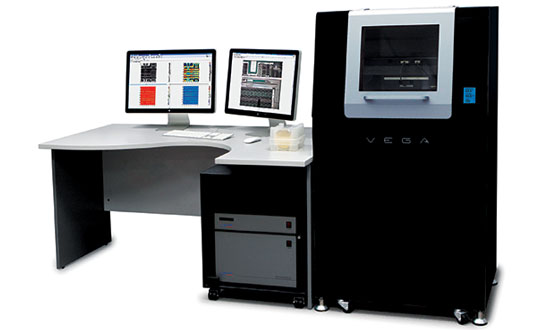
VEGA
The ultimate display quality is ensured by the use of built-in acoustic and vibration isolation, thermal stabilization, the industry's best sensitivity of the optical recording system and the unique design of the scanning probe system, which allows achieving atomic resolution in routine measurements.
In the basic configuration, 50+ AFM techniques are available, including the HybriD method, which allows conducting all cutting-edge nanomechanical, electrical and magnetic studies.
Intelligent ScanTronic™ algorithm for one-click optimization of scanning parameters, which allows for perfect relief measurements using the amplitude-modulation method, regardless of the operator's experience.
Automated examination of multiple samples using a simple user interface to create a point-by-point scanning scenario and a database for stored received images.
Control of samples with dimensions up to 200×200 mm and thickness up to 40 mm at any point of the surface with a positioning accuracy of 1 micron.
Wide customization possibilities: installation of additional optical equipment, development of specialized sample holders, combination with a transport system, automation of measurements and data analysis in accordance with customer requirements.
NT-MDT Spectrum Instruments
Zelenograd
Produced in: Moscow, Zelenograd
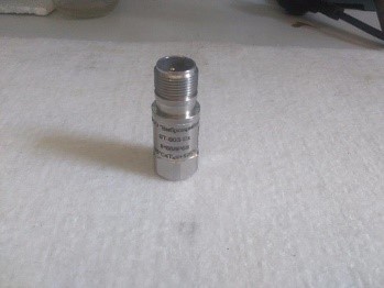
Vibration converter VT-003
The VT-003 vibration transducers are designed to convert the instantaneous value of the vibration acceleration of an object into an ICP signal of the IEEP standard.
VIBROPRIBOR
Yaroslavl
Produced in: Yaroslavl
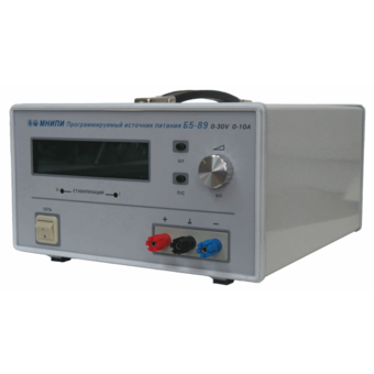
Power supply B5-89, B5-89/1
Technical specifications:
Indicator name, unit of measurement, Indicator value,
B5-89, B5-89/1
The range of the output voltage setting, the limits of the absolute error of the output voltage setting:- basic error, In; - in operating conditions, In, from 0 to 30.0 ± 0.2± 0.3, from 0 to 100.0 ± 0.3± 0.45
The range of the output current setting, the limits of the absolute error of the output current setting:- basic error, A; - in operating conditions, A, from 0 to 10.0 ± 0.2± 0.3, from 0 to 3.0 ± 0.1± 0.15
Instability of the output voltage when the supply voltage changes by ± 10% of the nominal value in the voltage stabilization mode, %, ± 0.05, no more,
Instability of the output current when the supply voltage changes by ± 10% of the nominal value in the current stabilization mode, %, ± 0.2, no more,
Instability of the output voltage when the load current changes at the output terminals of power supplies in voltage stabilization mode, %, ± 1, no more,
Instability of the output current when the load voltage changes in the current stabilization mode at minimum load currents, %, ± 5, no more,
Instability of the output current when the load voltage changes in the current stabilization mode at maximum load currents, %, ± 0.5, no more,
Output voltage ripple in voltage stabilization mode, mV, 1.0, no more,
Output current ripple in current stabilization mode, %, 1, no more,
Instability of the output voltage from time, V, ± 0.5, ± 1.0
Instability of the output current from time, A, ± 0.3, ± 0.2
AC power supply: - voltage, V; - frequency, Hz, 230 ± 2350 ± 0.5,
Weight, kg, 13.0, no more,
Overall dimensions, mm, 384x301x169
MNIPI
Minsk
Produced in: Belarus, Minsk
Metrological high-voltage laboratory of TECHNOAS
For primary and periodic verification and calibration at the field of operation of the following measuring instruments that are part of automated information and measurement systems for commercial accounting of electrical energy (AIIS KUE) or non-automated metering units:
• – Measuring voltage transformers (TN) of accuracy classes 0.2 and less accurate at loads normalized by GOST, and at real loads at the metering unit.
• – Measuring current transformers (TT) of accuracy classes 0.2S and less accurate with nominal primary currents of 100...5000 A (including high-voltage transformers for 330 kV lines) at loads standardized by GOST 7746-2001 and at real loads; single-phase and three-phase electric active and reactive energy meters of accuracy classes 0.2S and less accurate.
• – Auxiliary SI: ammeters, voltmeters, wattmeters, voltage, current and power converters, accuracy classes 0.2 and less accurate, phase meters, power factor meters of accuracy classes from 0.10 and less accurate.
• – Energy frequency meters of accuracy classes from 0.02 and less accurate, used at the electricity metering unit.
• – For measuring the load capacity of TN iTT.
• – For measuring voltage losses in secondary TN circuits.
– For measuring the quality of electrical energy (PCE) in accordance with the requirements of GOST 13109-97.
TEKHNO-AS
Kolomna
Produced in: Kolomna, Moscow region
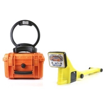
Cable Searcher Athlete AG-318N
from
259 800 ₽
A trace searching kit for finding underground utilities (cable lines, metal pipelines, and other communications made of conductive materials).
The kit includes a receiver in the form of a monoblock with LED indication, as well as the most powerful multi-frequency generator in the TECHNO-AC line, with a range of up to 10 km.
TEKHNO-AS
Kolomna
Produced in: Kolomna, Moscow region