Catalog
Search
213 products
View:
- Selected: 1Areas of use
- Selected: 0Item names
- Selected: 0Manufacturer
- Selected: 0Made in
- Selected: 0Additional
View:
213 products
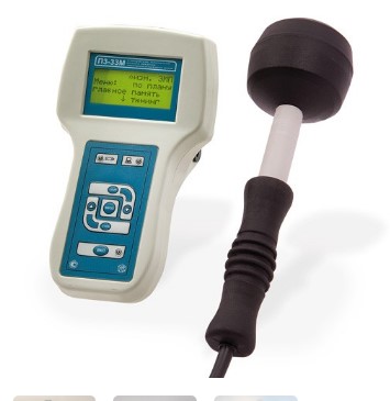
P3-33M Electromagnetic Field Energy Flux Density Meter
from
117 000 ₽
Meets the requirements of the US and German standards.
The energy flux density meter (PPE) of the electromagnetic field PZ-ZZM is designed to measure the PPE in continuous generation mode in the frequency range from 0.3 to 18 GHz when monitoring the levels of the electromagnetic field for compliance with the requirements of electromagnetic safety standards.
The meter is used to measure the levels of microwave radiation in residential and working premises in the presence of electrical equipment for power, household, switching and information purposes, as well as during a comprehensive sanitary and hygienic survey of territories. The meter is allowed to be used for work in the field.
The meter consists of an antenna-converter of the electromagnetic field energy flux density into a constant voltage and a measuring and display unit that performs analog-to-digital conversion, digital signal processing and output of measurement results to a liquid crystal display screen, as well as to a personal computer. The antenna of the meter has three dipole-detector microassemblies that form a mutually orthogonal structure. The resulting PPE value is defined as the vector sum of the PPE measured by each dipole microassembly
NMT-ZASHCHITA
Moscow
Produced in: Moscow
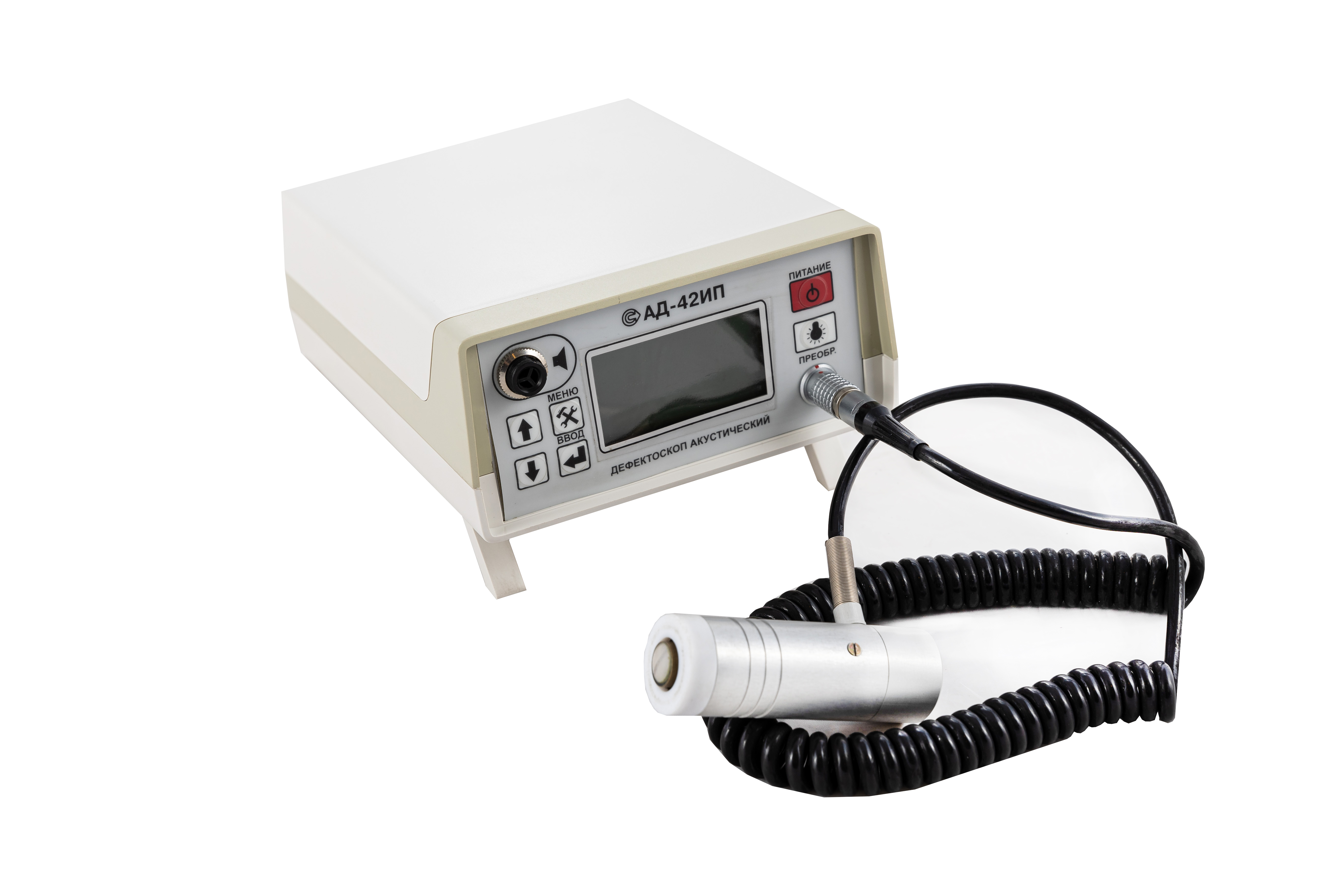
AD-42IP Acoustic Flaw Detector
from
442 500 ₽
It is especially effective for use in products made of composite materials (including with honeycomb filler).
Distinctive features:
The AD-42 IP is a compact acoustic system sensitive to changes in mechanical impedance caused by product defects. The indication of the device indicates that there are voids, non-adhesives, delaminations or changes in the structure of composite materials (including with honeycomb filler and laminated plastics) under the sensor.
The device is used to monitor various materials and their combinations.
The energy consumption of the unit is low because the converter is switched on when the sensor is placed on the monitored product.
Being light enough, the device allows you to perform monitoring in hard-to-reach places or in confined spaces.
The results of the control can be stored in the built-in non-volatile memory and transferred to a PC.
Converters
Options: - 3 types of converters for various tasks
Emitters: - 1 or 2 on each converter
Switching-on: - The converters are switched on when they are placed on a controlled object.
Technical characteristics:
Weight, kg: 0.73
Dimensions, mm: 210x150x70
Power supply: 4 AA batteries
Work without recharging the battery, h: 8
Battery discharge visual indication
The defect alarm is visual on the converter and audible on the instrument panel (or) in headphones.
RII MNPO SPEKTR
Moscow
Produced in: Moscow
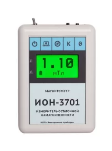
Magnetometer - Residual magnetization meter ION-3701
from
57 245 ₽
The small-sized digital magnetometer (Gaussmeter, teslameter), ION-3701 residual magnetization meter is a modern high-precision instrument, a further development of ION series devices (ION-1, ION-2, ION-2M, ION-7) and used for a wide range of tasks in areas where it is necessary to determine the magnitude of the magnetic field and residual magnetization. It is equipped with a three-dimensional magnetic field sensor and has outstanding technical characteristics and extensive functionality.
NPP "ELEKTRONNYE PRIBORY"
Naberezhnye Chelny
Produced in: Tatarstan, Naberezhnye Chelny
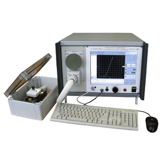
Meters of parameters of semiconductor devices IPPP-3, IPPP-3/1
General characteristics:
LCD screen 12.1" with a resolution of 1024 x 768, keyboard, mouse.
USB, Ethernet.
Supply voltage: 230 V / 50 Hz, power: 450 V·A.
Operating temperature range: from +5° to +40°C.
Dimensions (W x H x D): 470 x 330 x 570 mm, weight: 37 kg
MNIPI
Minsk
Produced in: Belarus, Minsk
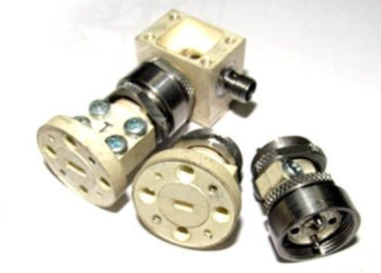
PS-78 (waves.)
Strobe converters are used as input devices of radio measuring equipment: amplifasometers, frequency meters, spectrum analyzers, circuit analyzers, etc.; in systems of synchronization and frequency stabilization of microwave generators, heterodynes, frequency synthesizers.
Basic properties:
Wide frequency range;
Minimal losses and uneven conversion;
High "decoupling" of channels;
Large dynamic range of input signals;
Harsh operating conditions
Operating conditions
Operating temperature range from minus 10 to 50 °C;
Relative humidity up to 98% at a temperature of 25 ° C.
Technical specifications
Frequency range:
• Microwave signal, GHz 37.5-78.33
• heterodyne, GHz 2.0-6.0
• IF, MHz 0-1000
Conversion losses *>, 30-40 dB by the 20th garm.
The power level of the heterodyne, dBm 20-22
Connector type:
• Microwave signal input P-waveguide with transitions to 5,2x2,6 and 3,6x1,8 mm
• 1HR heterodyne input
• IF output two woofer inputs
TEKHNOYAKS
Moscow
Produced in: Moscow
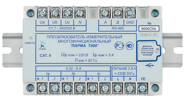
MULTIFUNCTIONAL MEASURING CONVERTER PARMA T400
Scope of application
· measurement of electrical energy parameters in three-phase or single-phase current networks with their subsequent transmission to the upper level of the AIS
· the device of the lower level in the AIS at the facilities of generation, conversion, transmission and distribution of electricity
PARMA
Saint Petersburg
Produced in: Saint Petersburg
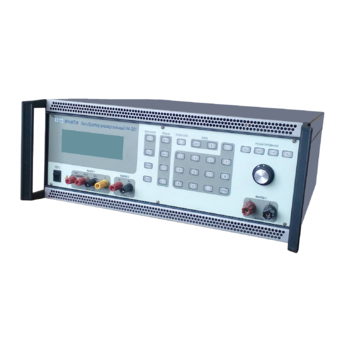
Universal calibrator H4-201
Technical specifications:
reproduction of DC voltage from 50 mv to 1000 V
- ranges of 200 mV; 2; 20; 200; 1000 V
- error 0.01 – 0.023 %
reproduction
of the sinusoidal AC voltage from 0.3 mV to 750 V
- ranges of 200 mV; 2; 20; 200; 750 V
- error 0.15 – 0.225 %
- frequency range 20 Hz - 100 kHz (20 Hz - 5 kHz on the range. 200 V; 20 Hz - 2.5 kHz on the range. 750 V)
reproduction of DC power from 0.03 µA to 50 A
- ranges of 200 Ma; 2; 20; 200 mA; 2; 50 A
- error 0.012 – 0.022 %
reproduction of AC power
of sinusoidal shape from 3 µA to 50 A
- ranges of 200 Ma; 2; 20; 200 mA; 2; 50 A
- error 0.062 – 0.23 %
- frequency range 20 - 5000 Hz (45 - 1000 Hz on the range. 50 A)
RS-232C interfaces; USB
operating temperature range from + 5 to +40oC
dimensions 184.5x465x540.5 mm
weight 20 kg
power supply ~ 230 V
MNIPI
Minsk
Produced in: Belarus, Minsk
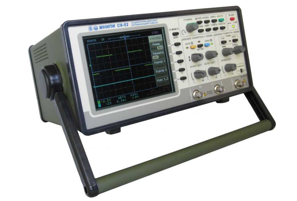
Digital oscilloscope S8-52
Designed to study and measure the parameters of electrical signals in the frequency band from 0 to 120 MHz.
Technical specifications:
Number of channels 2
120 MHz bandwidth
Sampling rate 250 MHz
Equivalent sampling rate of 10 GHz
Rise time of PH <= 2.9 ns
Input active resistance (1±0.02) Mom
Input capacitance <= 25 pF
120 MHz bandwidth
2 channels, external synchronization input
Vertical sensitivity 2 mV/div
Sampling rate up to 250 Mbps, in real time
Recording length up to 16K counts in each channel
Color LCD screen with LED backlight
Cursor and automatic measurements
USB and RS-232 interface
MNIPI
Minsk
Produced in: Belarus, Minsk
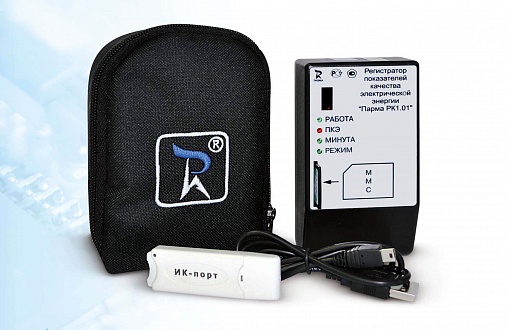
ELECTRICITY QUALITY RECORDER PARMA RC1.01
Appointment. Scope of application
· continuous monitoring of the 220 V network
· identification of problems with power supply in a single apartment, company or HOA
· conducting inspections and finding out the source of deterioration in the quality of electricity in apartment buildings, in HOA, in business centers
· formation of an expert base when resolving (in court or pre-trial) conflicts between energy marketing organizations and consumers - individuals
· justification of the reasons for the failure of expensive household appliances from consumers
PARMA
Saint Petersburg
Produced in: Saint Petersburg

VD-7.2×3.4
A flexible waveguide is a piece of high-quality dielectric, which ends with transitions to standard waveguides with flanges.
For ease of operation, the waveguide is protected by an elastic shell.
Basic properties
Manufacturability of the connection;
Small losses and VSWR;
Economy.
Operating conditions
Operating temperature range from 5 to 50 ° C;
The relative humidity of the air is up to 98% at a temperature of 25 ° C.
Technical specifications
Waveguide cross section, mm 7.2×3.4
Flange type according to GOST RV 51914-2002
Frequency range, GHz 25.95-37.50
VSWR 1.25
Losses, dB 2.0
Length, mm* 500
TEKHNOYAKS
Moscow
Produced in: Moscow
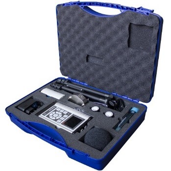
ASSISTANT-TOTAL+ (a set of instruments in a plastic case)
from
345 000 ₽
Measurement of sound levels, sound pressure and frequency analysis in the ranges of sound, infrasound and ultrasound, levels of vibration acceleration and frequency analysis in the ranges of general and local vibration on 3 channels simultaneously.
NMT-ZASHCHITA
Moscow
Produced in: Moscow
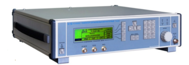
High-frequency signal generator G4-230
The generator is capable of operating both autonomously and as part of automated measuring systems with USB and IEEE-488 (CPC) interfaces.
Technical specifications
Frequency range from 5 to 17.85 GHz
Frequency tuning discreteness 0.001 Hz
The main error of the frequency setting is ± 3x10⁻⁷ Hz
The range of setting the output signal power level at the main output is from minus 110 to 13 dBm
The basic error of setting the reference power level is ± 1.0 dB
Instability of the output signal power level for any 15-minute time interval of no more than 0.1 dB
Metrological characteristics of the generator in the FM operation mode:
- frequency range of the modulating signal:
low frequency from 1 Hz to 20 kHz
RFM from 10 to 100 kHz
- frequency deviation setting range (taking into account the carrier frequency value):
low frequency from 1 Hz to 100 kHz
RFM from 50 to 10000 kHz
- the main error of the frequency deviation setting is ± (3 – 18)%
Metrological characteristics of the generator in AM operation mode:
- frequency range of the modulating signal from 0.05 to 5.0 kHz
- the range of setting the amplitude modulation coefficient from 1 to 50 %
- the main error in setting the amplitude modulation coefficient:
Internal ± (0.15M + 0.2)%
External ± (0.20M + 0.5)%
Metrological characteristics of the generator in the IM operation mode:
- the duration range of modulating pulses from 100 ns to 20 s
- the range of the modulating pulse repetition period from 140 ns to 30 s
- the difference in the duration of the output RF pulses from the duration of the modulating pulses ± 100 ns
Operating temperature range from minus 10 to 40 °C
AC power supply 220 V, 50 Hz
Power consumption, no more than 150 VA
Overall dimensions, mm 498x136x487
Weight, not more than 15 kg
TEKHNOYAKS
Moscow
Produced in: Moscow
