Catalog
Metrology
525 products
View:
- Selected: 0Areas of use
- Selected: 0Item names
- Selected: 0Manufacturer
- Selected: 0Made in
- Selected: 0Additional
View:
525 products
Oscilloscope S1-167/2
Designed for the study of periodic electrical signals by visual observation and measurement of their amplitude and time parameters on the scale of the CRT screen in the frequency band 0 - 25 MHz with a built-in multimeter measuring voltage and DC power, the average square value of voltage and AC power, DC electrical resistance.
Technical specifications:
Vertical deviation
Number of channels 2
Bandwidth 0-25 MHz
Deviation coefficients 2 mV/div-10 V/div (step 1-2-5)
Installation error ± 3%
Rise time of PH <= 14 nsec
Input impedance 1 mOhm/23 pF, with divider 1:10-10 mOhm/12 pF
with open input <=110 V
with closed input <=110 V
with divider 1:10 <= 250 V
range U post. U AC: 1 mV–500 V
Error 0.1% (U post); 0.3% -1% (U perem. 40 Hz–100 kHz)
Range I post., I AC.: 1 mA–2 A
Error: 0.25% (I post.); 0.5% (I perem. 40 Hz–5 kHz)
R Range: 1 Ohm–1 mOhm
Error R: 0.2%
3.5-digit indicator
Automatic selection of limits.
MNIPI
Minsk
Produced in: Belarus, Minsk
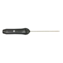
Smart probe submersible reinforced L=1500 mm SZPGU.1500
from
14 490 ₽
The Smart submersible reinforced probe L=1500 mm SZPGU.1500 is designed to measure the temperature of various materials by direct contact of the probe with the measuring object and transmitting the measured value via Bluetooth to devices with the ThermoMonitor, Android program installed.
Operating conditions of the SZPGU.1500 smart probe
Ambient temperature, °C: -20...+55.
Relative humidity, %: not more than 80 at T=35 °C.
Atmospheric pressure, kPa: 86...106.
Functionality of the smart probe SZPGU.1500
Measurement of physical quantities with a resolution of 0.01.
Recording of measured values at intervals from 5 seconds to 23 hours 59 minutes 59 seconds (only smart probes with built-in memory).
Transmitting data about measured physical quantities via Bluetooth to a device with the ThermoMonitor, Android program installed.
Transmitting information about the state of charge of the built-in battery via Bluetooth to a device with the ThermoMonitor, Android program installed.
Automatic transition to sleep mode after 50 seconds.
The ability to connect an external power supply.
Possibility of calibration.
TEKHNO-AS
Kolomna
Produced in: Kolomna, Moscow region
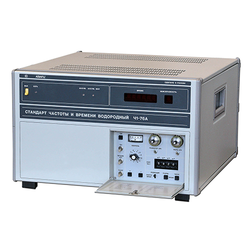
Frequency and time standard hydrogen Ch1-76A
NNPO im. M.V.Frunze
Nizhny Novgorod
Produced in: Nizhny Novgorod
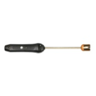
Surface smart probeL=500 mm SZPV.500P with built-in flash memory
from
15 249 ₽
The surface smart probe L=500 mm SZPV.500 is designed to measure the temperature of various materials by direct contact of the probe with the measuring object and transmitting the measured value via Bluetooth to devices with the ThermoMonitor based on the Android program.
Operating conditions of the SZPV.500 smart probe
Ambient temperature, °C: -20...+55.
Relative humidity, %: not more than 80 at T=35 °C.
Atmospheric pressure, kPa: 86...106.
Functionality of the SZPV.500 smart probe
Measurement of physical quantities with a resolution of 0.01.
Recording of measured values at intervals from 5 seconds to 23 hours 59 minutes 59 seconds (only smart probes with built-in memory).
Transmitting data about measured physical quantities via Bluetooth to a device with the ThermoMonitor based on the Android program.
Transmitting information about the state of charge of the built-in battery via Bluetooth to a device with the ThermoMonitor based on the Android program.
Automatic transition to sleep mode after 50 seconds.
The ability to connect external power.
Possibility of calibration.
TEKHNO-AS
Kolomna
Produced in: Kolomna, Moscow region
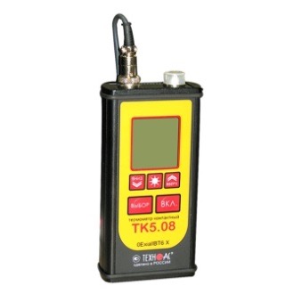
Contact thermometer TK-5.08 with the function of measuring relative humidity (explosion-proof)
from
43 200 ₽
A unique, reliable device with a huge number of replaceable probes.
The contact thermometer TK-5.08 is designed to solve problems of any complexity with the highest accuracy in the field of measuring the temperature of flammable liquids, bulk substances, air, explosive gas mixtures, solid surfaces and relative humidity of the air-gas environment at oil and gas and chemical industry enterprises.
Shock-resistant and frost-resistant design allows you to operate the device in harsh climatic conditions.
TEKHNO-AS
Kolomna
Produced in: Moscow
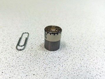
Microphone condenser capsule MK-265
It is designed to measure sound pressure in the air and is used in noise measuring equipment as a measuring transducer of infrasound, sound and ultrasonic pressure.
VIBROPRIBOR
Yaroslavl
Produced in: Yaroslavl
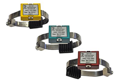
PARMA KMT TEMPERATURE MONITORING COMPLEX
The temperature monitoring complex "PARMA KMT" is designed for:
• implementation of continuous wireless multi-channel monitoring of temperatures of controlled objects and the environment
• issuing alarms when the threshold values (setpoints) of dangerous and emergency overheating are reached by temperature and dangerous overheating rate
• detection of temperature differences on the same type of connections
• display of the measured temperature and the control point
• transmission of telemetry data to top-level devices in automated control systems via Modbus protocol for processing, archiving and analysis of measurements
• archiving, displaying and analyzing data, identifying trends and developing defects at the PS, RES level based on the proposed parameterized SCADA
The temperature monitoring complex "PARMA KMT" is installed in switchgears (RC) with a voltage from 0.4 to 35 kV in the places of movable contacts, busbars, transformer inputs, cables and their connections with busbars.
PARMA
Saint Petersburg
Produced in: Saint Petersburg
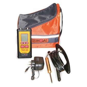
Oilman's Kit-1
from
67 254 ₽
It is designed to measure the temperature during the transportation of petroleum products, namely, to make a temperature correction for the volumetric expansion of petroleum products. The density of petroleum products decreases significantly with increasing temperatures, and the volume of the product increases, the kit "Oilman-1" allows temperature measurements for the subsequent calculation of the volumetric expansion of petroleum products.
•
TEKHNO-AS
Kolomna
Produced in: Moscow
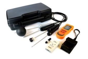
"Home officer" Profi Kit
from
80 025 ₽
Designed to measure the temperature and humidity of indoor air, the surface of heating appliances, water temperature in heating and hot water systems.
•
TEKHNO-AS
Kolomna
Produced in: Moscow
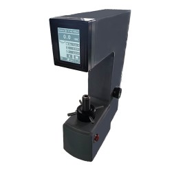
Metolab 102 Rockwell Hardness Tester
METOLAB 102 is a stationary hardness tester, a modification of the METOLAB 100 and METOLAB 101 devices with extended functional characteristics. The main difference of this model is a fully automated measurement process. The METOLAB 102 hardness tester allows you to control the parameters of various materials and products using the Rockwell method, HRA, HRB, HRC scales.
It is also worth mentioning the opportunity to print promptly measurement results on the built-in printer, the functional opportunity to convert the results into the Vickers, Brinell and Super-Rockwell scales.
Structurally, the METOLAB 102 hardness tester is a stationary device consisting of a load application mechanism and the measuring unit itself. The principle of operation of the device is based on the indentation of a diamond cone or steel ball tip into the material under study, followed by measurement of the resulting print. Due to its ease of operation, the stationary METOLAB 100 hardness tester can find its application in a wide variety of industries and production, as well as in educational institutions of various levels in the training of specialists.
The stationary METOLAB 102 Rockwell hardness tester is included in the State Register of Measuring Instruments of Russia (GRSI) and comes with a certificate of primary verification (on request). The number in the GRSI is 65128-16.
Distinctive features of the stationary METOLAB 102 Rockwell hardness tester:
Simplicity and convenience in operation and maintenance;
Large and bright LCD screen, fully Russian-language menu, output of all necessary information;
Wide range of measured values;
Ability to convert results to Brinell, Vickers, Super-Rockwell scales;
Built-in printer for quick printing of measurement results;
High degree of reliability of the hardness tester.
Basic delivery package:
Stationary METOLAB 102 hardness tester;
Indenter with a ball (1.5875 mm) - 1 pc.;
Conical diamond indenter (120°) - 1 pc.;
Flat table SP1 (60 mm);
V-shaped prismatic table SRP1 (40 mm);
Rockwell hardness measures - 1 set;
User Manual.
Metolab
Moscow
Produced in: Moscow
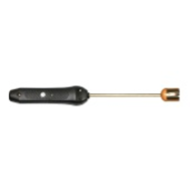
Surface smart probe L=1000 mm SZPV.1000P with built-in flash memory
from
13 920 ₽
The surface smart probe L=1000 mm SZPV.1000P with built-in flash memory is designed to measure the temperature of various materials by direct contact of the probe with the measuring object and transmitting the measured value via Bluetooth to devices with the ThermoMonitor based on the Android program.
Operating conditions of the SZPV.1000P smart probe
Ambient temperature, °C: -20...+55.
Relative humidity, %: not more than 80 at T=35 °C.
Atmospheric pressure, kPa: 86...106.
Functionality of the SZPV.1000P smart probe
Measurement of physical quantities with a resolution of 0.01.
Recording of measured values at intervals from 5 seconds to 23 hours 59 minutes 59 seconds (only smart probes with built-in memory).
Transmitting data about measured physical quantities via Bluetooth to a device with the ThermoMonitor based on the Android program.
Transmitting information about the state of charge of the built-in battery via Bluetooth to a device with the ThermoMonitor based on the Android program.
Automatic transition to sleep mode after 50 seconds.
The ability to connect an external power supply.
Possibility of calibration.
TEKHNO-AS
Kolomna
Produced in: Kolomna, Moscow region
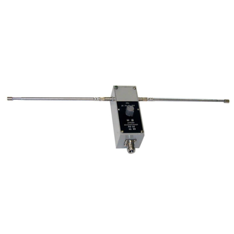
Measuring antenna P6-61
Technical specifications:
Frequency range (26.0 - 300) MHz
SWR < 2
The limit of permissible error of the antenna coefficient, not more than ± 2.0 dB
Orthogonal polarization signal level -20 dB
Ambient air temperature from - 50 to + 60
Relative humidity of 95 % at + 35 ° C
Overall dimensions (HxWxD) 145x75x1720 mm
Weight 0.7 kg
MNIPI
Minsk
Produced in: Belarus, Minsk
