Language selection
В настоящее время портал работает - ведутся технические работы.
Catalog
Search
246 products
View:
- Selected: 1Areas of use
- Selected: 0Item names
- Selected: 0Manufacturer
- Selected: 0Made in
- Selected: 0Additional
View:
246 products
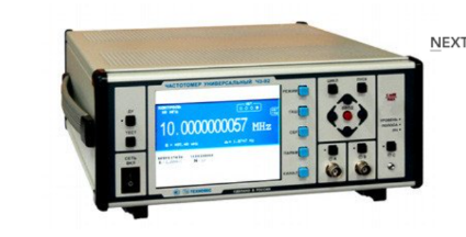
Universal frequency meter Ch3-92
The frequency meter is able to work both independently and as part of automated measuring systems with interfaces such as USB or RS-232.
Technical specifications
Frequency and period of sinusoidal signals (inputs A, B) 0.001 Hz - 300 MHz
Frequency and period of video pulse signals (inputs A, B) 0.001 Hz - 300 MHz
Frequency of continuous sinusoidal oscillations (input C) (0.3 – 37.5) GHz
Pulse duration 10 ns - 1000 s
The duration of the front, the decay of the pulses is 5 ns - 100 microseconds
Time interval from -1000 to 1000 s
Frequency measurement resolution 2x10⁻¹⁰ s/Rng
The range of setting the trigger levels (inputs A, B) from minus 2.5 to 2.5 V
The error of setting the trigger levels (inputs A, B) ± 0.05 V
Input signal level:
• for sinusoidal signal (inputs A, B) (0.03 - 10.0) V
• for video pulse signal (inputs A, B) (0.1 - 10.0) V
• for sinusoidal signal (input C) 50 MW - 5 MW
Input resistance
• Inputs A, B (50±2.5) ohms; (1±0.1) MOm/100 pF
• Input With (50±2.5) ohms
Nominal frequency value of the reference quartz oscillator 10 MHz
Relative error in the frequency of the quartz oscillator, no more than ± 2x10⁻⁷ in 12 months
Operating temperature range from minus 10 to 40 °C
AC power supply 220 V, 50 Hz
Power consumption, not more than 100 VA
Overall dimensions, mm
299x136x436,5
Weight, not more than 8.5 kg
TEKHNOYAKS
Moscow
Produced in: Moscow
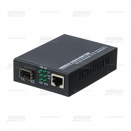
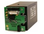
Media Converter SFP - SFP MCSFP2 - SFP
from
2 193 ₽
A media converter is used as a converter that converts one signal transmission medium into another. The data transmission medium means optical and copper cable. The scope of application – FastEthernet and GigabitEthernet protocols, STM-1 and STM-4. Media converters are characterized by a number of parameters, by setting that you can choose the optimal network equipment for solving a specific task.
The possibility to control the device;
Installation location;
Properties of the optical receiver-transmitter;
Supported transfer rate.
FTI-Optronik
Saint Petersburg
Produced in: Saint Petersburg
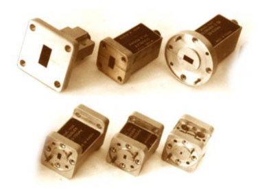
UCHX2-78
Basic properties:
Wide frequency range;
Sufficiently large output power;
High level of suppression of side harmonics of the input signal;
Low phase noise value;
Relatively simple technical solutions:
- synchronization and frequency stabilization,
- stabilization and adjustment of the output power level,
- implementation of amplitude and frequency modulation modes;
Do not require external bias diodes.
Operating conditions:
Operating temperature range from minus 10 to 50 ° C;
The relative humidity of the air is up to 98% at a temperature of 25 ° C.
Technical characteristics
Input/output frequency range, GHz 26,78-39,17 / 53,57-78,33
Losses (max.), dB 15
Input power level, dBm 15-21
Unevenness of output power (Rvh. = 20 dBm), dB ± 2.0
The level of parasitic harmonics of the input signal at the output (min.), dBn 20
Output VSWR (max.) 2.0
Connector type:
• Input Coax. 2.4/1.0 mm (plug/socket)
• Output Waveguide 3,759x1,88 mm (50-75GGo)
Overall dimensions, mm 26x20x20
Weight, g 50
TEKHNOYAKS
Moscow
Produced in: Moscow
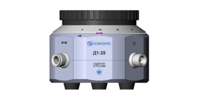
Measuring step attenuator D1-29
The device replaces the devices for checking the attenuators D1-13A and D1-25.
D1-29 is a step attenuator with a range of attenuation from 0 to 110 dB with a step of 10 dB, operating in the frequency range from 0 to 150 MHz.
The device consists of a housing with damping cells and a switch with a counting device. The housing contains coaxial input and output connectors, as well as additional connectors "40 dB" and "80 dB", necessary for the verification of the device.
Technical specifications
Operating frequency range 0 – 150 MHz
Difference attenuation setting range (after 10 dB) 0 – 110 dB
Input electrical resistance to direct current 50 ± 0.1 ohms
The output electrical resistance to direct current when connected to the load input is 50 ± 0.1 ohms 25 ± 0.1 ohms
The main absolute error of the difference attenuation setting relative to the 0 dB mark at direct current ± (0.002 - 0.02) dB
The main absolute error of the difference attenuation setting relative to the 10 dB mark in the frequency range up to 30 MHz ± (0.004 - 0.9) dB
The main absolute error of the difference attenuation setting relative to the 10 dB mark in the frequency range over 30 to 150 MHz ± (0.09 - 3.0) dB
The maximum permissible value of the electrical voltage (DC or AC) at the input of the attenuator 3 In
the operating temperature range from 5 to 40 ° C
Overall dimensions, mm 149x95x149
Weight, not more than 3 kg
TEKHNOYAKS
Moscow
Produced in: Moscow
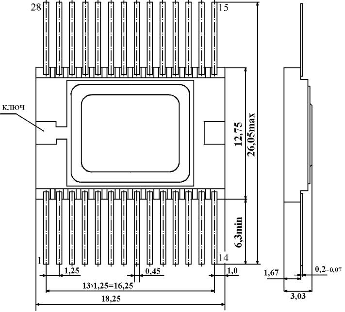
AF011B Microassembly
A high-speed signal limiter amplifier.
Designed for use in electronic counting frequency meters.
Description:
The magnitude of the input signals for selecting the switch input and inverting the signal of the limiter amplifier at a supply voltage of ± 5 V:
- logical "0"
not more than 0.2 V;
- logical "1"
at least 4.8 V.
The value of the input signals of switching on / off the switch at a supply voltage of ± 5 V:
- logical "0"
no more than 3.3 V;
- logical "1"
at least 4.1 V.
The magnitude of the output signals of the switch at a supply voltage of ± 5 V and a load of 300 ohms connected to zero potential:
- logical "0"
from 3.1 V to 3.4 V;
- logical "1"
from 4.0 V to 4.3 V.
The minimum input voltage of the sinusoidal shape in the frequency range from 10 Hz to 200 MHz should be no more than 30 mV.
The maximum input voltage of the sinusoidal shape in the frequency range from 10 Hz to 200 MHz must be at least 1 V.
The value of the supply voltage:
- positive
5±0.2 V;
- negative
-5±0.2 V.
The current consumption should be no more than:
- from a positive power source
110 mA;
- from a negative power supply
35 mA.
MNIPI
Minsk
Produced in: Belarus, Minsk
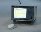
Frequency comparator CHK7-1011
Frequency comparators CHK7-1011 and CHK7-1011/1 can also be used as frequency and time standards with frequency correction based on GLONASS/GPS signals as sources of highly stable signals in various frequency measuring systems.
Comparators have a built-in device for processing measurement data based on a microcomputer, which provides statistical processing of the results of frequency and time measurements, and a device for displaying information based on a color TFT display. The built-in diagnostic system allows you to quickly determine the operability and condition of the main comparator devices with information output to the built-in display screen.
Comparators are available in three versions and differ in composition and functions performed. Comparators have a basic set of devices (modules), including a frequency comparator, a power supply module and a device for processing and displaying information based on a microcomputer and a color TFT display.
The frequency comparator CHK7-1011 has a built-in SRNS receiver and a highly stable rubidium frequency standard Ch1-1014 with the function of correcting the actual frequency value by signals from satellite radio navigation systems GLONASS or GPS. The comparator forms its own time scale with the ability to synchronize on any external time scale received by the SRNS receiver built into the device. The device has two modes for measuring the deviation of the generated time scale: from the time scale of the built-in SRNS receiver and from the external time scale. Information about the current time received from the SRNS receiver is displayed on the comparator display screen, and is also transmitted to the consumer via the RS-485 interface.
All the above-mentioned features make the frequency comparator CHK7-1011 a unique measuring device in the field of frequency and time measurements.
The frequency comparator CHK7-1011/1 has a highly stable rubidium frequency standard Ch1-1013 and can be used as a frequency and time standard as a source of highly stable signals in various frequency measuring systems.
The frequency comparator CHK7-1011/2 does not include any additional devices. To carry out measurements with it, it is necessary to use a highly stable signal of the reference frequency from an external RF or hydrogen frequency standard.
For the convenience of users, apart from the keypad, they can also exercise control of the functions of the devices with a mouse-type manipulator included in the delivery package. Comparators provide access to measurement data over an Ethernet network.
Ruknar
Nizhny Novgorod
Produced in: Nizhny Novgorod
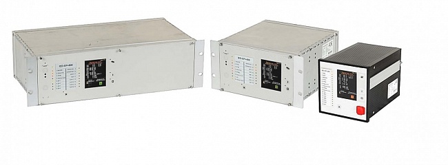
RELAY PROTECTION UNITS FOR DIGITAL SUBSTATION OF THE IED-EP+ SERIES
A series of modern intelligent relay protection, automation and alarm units PARMA IED-EP+ is designed for use in networks with a voltage from 6 to 750 kV
PARMA
Saint Petersburg
Produced in: Saint Petersburg
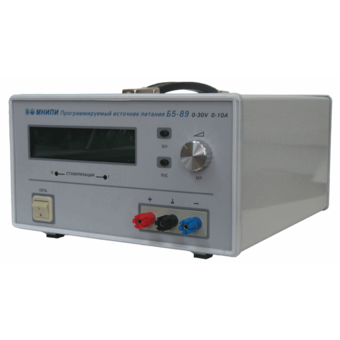
Power supply B5-89, B5-89/1
Technical specifications:
Indicator name, unit of measurement, Indicator value,
B5-89, B5-89/1
The range of the output voltage setting, the limits of the absolute error of the output voltage setting:- basic error, In; - in operating conditions, In, from 0 to 30.0 ± 0.2± 0.3, from 0 to 100.0 ± 0.3± 0.45
The range of the output current setting, the limits of the absolute error of the output current setting:- basic error, A; - in operating conditions, A, from 0 to 10.0 ± 0.2± 0.3, from 0 to 3.0 ± 0.1± 0.15
Instability of the output voltage when the supply voltage changes by ± 10% of the nominal value in the voltage stabilization mode, %, ± 0.05, no more,
Instability of the output current when the supply voltage changes by ± 10% of the nominal value in the current stabilization mode, %, ± 0.2, no more,
Instability of the output voltage when the load current changes at the output terminals of power supplies in voltage stabilization mode, %, ± 1, no more,
Instability of the output current when the load voltage changes in the current stabilization mode at minimum load currents, %, ± 5, no more,
Instability of the output current when the load voltage changes in the current stabilization mode at maximum load currents, %, ± 0.5, no more,
Output voltage ripple in voltage stabilization mode, mV, 1.0, no more,
Output current ripple in current stabilization mode, %, 1, no more,
Instability of the output voltage from time, V, ± 0.5, ± 1.0
Instability of the output current from time, A, ± 0.3, ± 0.2
AC power supply: - voltage, V; - frequency, Hz, 230 ± 2350 ± 0.5,
Weight, kg, 13.0, no more,
Overall dimensions, mm, 384x301x169
MNIPI
Minsk
Produced in: Belarus, Minsk
Rubidium Ch1-1014 Frequency Standard with GPS/GLONASS Signal Receiver Module
The signals of the navigation receiver's second mark and the RF available for the customer`s use are generated simultaneously on two high-frequency outputs of the receiver board. In the presence of stable reception of signals from satellites of the GLONASS and GPS radio navigation systems, the board ensures the operation of the RF in the frequency binding mode according to the signals of the second timestamp (the so-called “disciplined” rubidium frequency standard mode) with a relative error of the actual value of the RF frequency of no more than ± 5.0.10-12.
Ruknar
Nizhny Novgorod
Produced in: Nizhny Novgorod
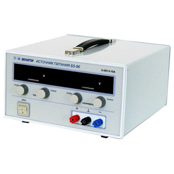
Power supply B5-86, B5-86/1
Main Features:
Output voltage indication error, ± 0.3 V
Output current indication error, ±0.06 A
Instability of the output voltage
due to changes in the supply voltage, 0.05%
Instability of the output current from a change
in the supply voltage, 0.2%
Instability of the output voltage when
the load current changes, 0.1 %
Instability of the output current when
the load voltage changes, 5.0 %
Output voltage ripple, mV 1.0
MNIPI
Minsk
Produced in: Belarus, Minsk
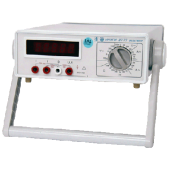
Voltmeter V7-77
Technical specifications:
DC voltage ,
Measuring range, 10 mv-1000V
Measurement error, ± (0.05% +4 E.M.R.)
AC voltage ,
Measuring range, 1 mV - 750 V
Measurement error, ± (0.5% +4 E.M.R.)
Frequency range, 20 Hz- 100 kHz
Direct current ,
Measuring range, 0.1 µA - 10 A
Measurement error, ± ( 0.25% +4 E.M.R.)
MNIPI
Minsk
Produced in: Belarus, Minsk

Frequency comparator Ch7-1014
Since it is reliable and easy to operate, the device is widely used in metrological centers, measuring laboratories, at the workplaces of REA developers.
The comparator Ch7-1014 has a communication interface with an external personal computer USB 2.0 and application software for an external PC.
At the request of the customer, the comparator can be supplied complete with a laptop or tablet computer with installed software.
Ruknar
Nizhny Novgorod
Produced in: Nizhny Novgorod