Catalog
Search
210 products
View:
- Selected: 1Areas of use
- Selected: 0Item names
- Selected: 0Manufacturer
- Selected: 0Made in
- Selected: 0Additional
View:
210 products
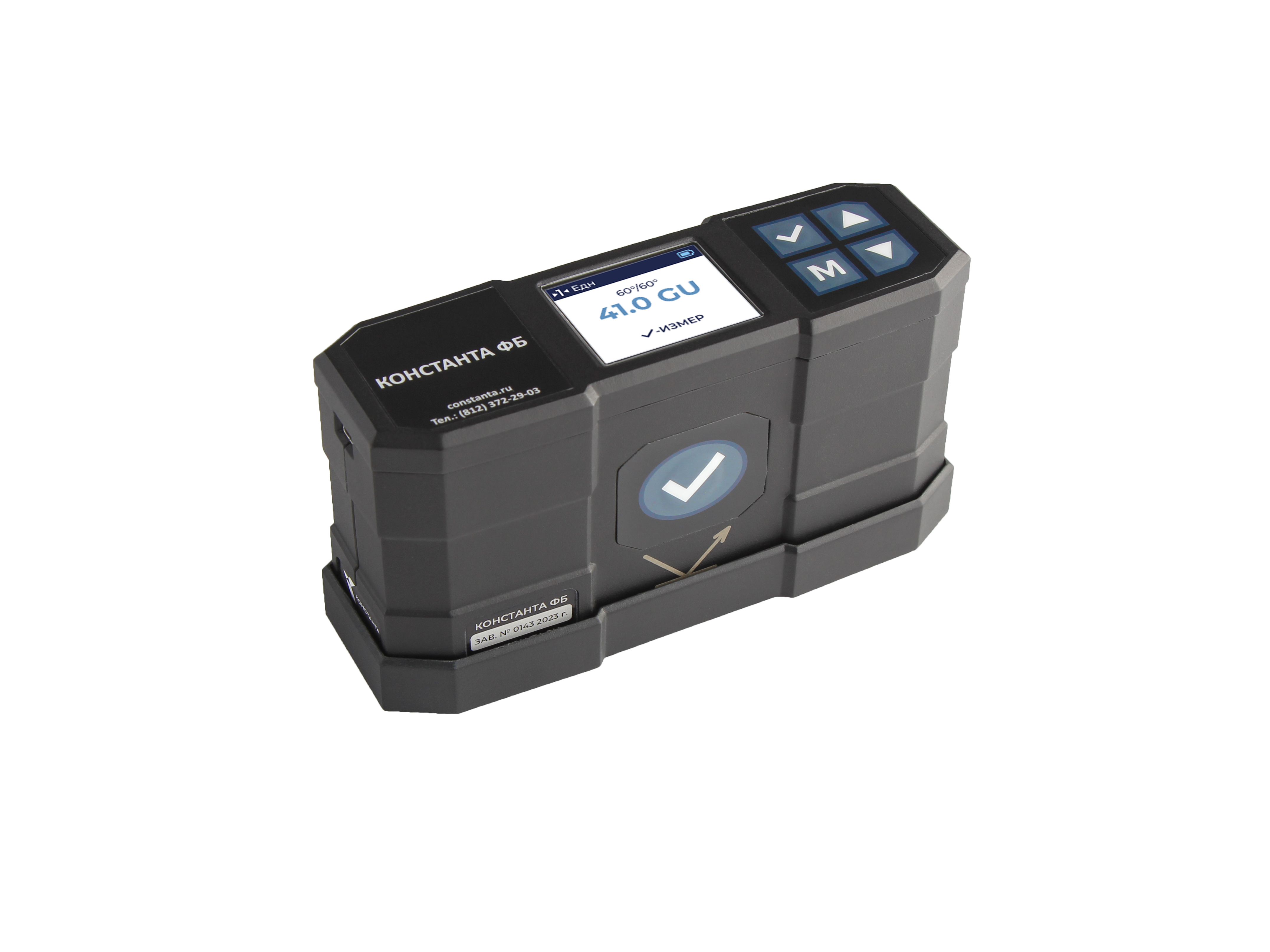
VOLTAMMETER PARMA VAF-A(M2)
It will help relay protection and automation services, the chief power engineer of industrial enterprises and a wide range of specialists engaged in setting up, monitoring, diagnostics and operation of electrical installations to solve the following tasks:
− control phase alternation
− remove the voltage characteristics
− measure phase shift angles and build vector diagrams of voltage and current
− control the circuits in the SHPT
− check the integrity of electrical conductors
− carry out operational maintenance of relay protection circuits and power circuits of electrical installations
− monitor the condition and diagnose DC circuits
− carry out phasing when setting up differential protection and connecting current and voltage transformers, electric motors
− check the correct connection of electricity meters
− determine the harmonic composition of current and voltage (up to and including the 19th harmonic)
PARMA
Saint Petersburg
Produced in: Saint Petersburg
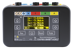
INSULATION PARAMETER METER PARMA TENSOR-2
PARMA TENSOR-2 (AC bridge) is designed for automatic measurements of:
· capacitance and tangent of the dielectric loss angle of high-voltage insulation of capacitors, inputs, transformers using an external high-voltage capacitor, both in laboratory and in the "field" conditions
· effective values of the first harmonic of the current and voltage of the industrial frequency
· the angle of phase shift between the signals supplied to the inputs of the device
· network frequencies
* Measurements can be carried out according to the "straight" and "inverse" (inverted) scheme.
* Allocates the vector of the influence current, which makes it possible to dispense with the phase regulator of the test voltage source or devices for compensating the influence current.
PARMA
Saint Petersburg
Produced in: Saint Petersburg
Rubidium frequency and time standards H1-1011/1
The modular construction principle makes it easy to adapt the devices to the specific requirements of the consumer. The standards are available in four versions – H1-1011, H1-1011/1, H1-1011/2 and H1-1011/3, which differ in metrological characteristics and a set of installed devices (modules). The built-in diagnostic system allows you to quickly determine the operability and condition of the main devices of the standards.
On the front panel of the devices H1-1011 and H1-1011/2 there is an LCD display and a control panel, with which you can quickly receive information about the current parameters of the devices included in the devices and adjust the frequency of the output signals.
The H1-1011 and H1-1011/2 standards can receive chronometric information from GLONASS and GPS satellite radio navigation systems and use it to synchronize the local time scale and automatically adjust the actual frequency value of the built-in highly stable rubidium frequency standard.
The H1-1011 and H1-1011/2 standards include:
rubidium frequency standard H1-1014;
MPR-01 satellite radio navigation systems receiver module;
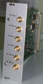
amplifier module for highly stable sinusoidal signals (at the customer's choice):
MUS-01 (3 independent outputs 10 MHz, connector type SR-50-73FV);
MUS-02 (3 independent outputs of 5 MHz, connector type SR-50-73FV);
MUS-03 (3 independent outputs of 1, 5 and 10 MHz, connector type SR-50-73FV);
MUS-04 (6 independent outputs of 1, 5 and 10 MHz in any combination at the customer's choice, SMA connector type);
MS synthesizer module with software (SMA connector type) instead of an amplifier module (at the customer's request).
The scope of delivery (at the request of the customer) includes an antenna for the SRNS receiver as part of:
antenna unit;
mounting device;
antenna cable (maximum length 60 m).
The H1-1011/1 and H1-1011/3 standards include:
the rubidium frequency standard H1-1013;
two modules of amplifiers of highly stable sinusoidal signals (at the customer's choice):
MUS-01 (3 independent outputs 10 MHz, connector type SR-50-73FV);
MUS-02 (3 independent outputs of 5 MHz, connector type SR-50-73FV);
MUS-03 (3 independent outputs of 1, 5 and 10 MHz, connector type SR-50-73FV);
MUS-04 (6 independent outputs of 1, 5 and 10 MHz in any combination at the customer's choice, SMA connector type);
MS synthesizer module with software (SMA connector type) instead of an amplifier module (at the customer's request).
Ruknar
Nizhny Novgorod
Produced in: Nizhny Novgorod
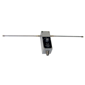
Measuring antenna P6-61
Technical specifications:
Frequency range (26.0 - 300) MHz
SWR < 2
The limit of permissible error of the antenna coefficient, not more than ± 2.0 dB
Orthogonal polarization signal level -20 dB
Ambient air temperature from - 50 to + 60
Relative humidity of 95 % at + 35 ° C
Overall dimensions (HxWxD) 145x75x1720 mm
Weight 0.7 kg
MNIPI
Minsk
Produced in: Belarus, Minsk

Measuring antenna P6-23M
Technical specifications:
Frequency range (0.85 - 17.44 GHz)
Standing Wave Coefficient (SWR) < 1.7
Effective area at least in the frequency range - from 0.85 to 15 GHz > 150 cm2 - from 15 to 17.44 GHz > 110 cm2
The margin of error of the effective area in the frequency range, no more - from 0.85 to 8.5 GHz ± 20% - from 8.5 to 17.44 GHz ± 15%
Orthogonal polarization signal level -25 dB
The level of the side lobes, no more than -10 dB
Ambient temperature -50°C - 50°C
Gabbar dimensions (HxWxD) 887x351x265 mm
Weight 6,8 kg
MNIPI
Minsk
Produced in: Belarus, Minsk
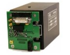
Navigation Systems Receiver module
On the two high-frequency outputs of the receiver board, the signals of the second mark of the navigation receiver and the RF, which are available for the customer`s use, are generated.
When receiving signals from satellites of the GLONASS and GPS radio navigation systems, the board ensures the operation of the RF in the frequency binding mode according to the signals of the second timestamp (the so-called “disciplined” rubidium frequency standard mode) with an error of the actual value of the RF frequency for no more than ± 5.10-12
Ruknar
Nizhny Novgorod
Produced in: Nizhny Novgorod
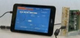
Frequency Synthesizer Module
Designed in the form of a module, standard for RUKNAR CJSC, it can be installed in any modular device of our production, elevating its functionality to a fundamentally new level.
The synthesizer module consists of three independent devices: a frequency synthesizer, a standard signal generator and a time scale generator.
The module has external control via USB 2.0 interface from a personal or tablet computer.
Ruknar
Nizhny Novgorod
Produced in: Nizhny Novgorod
Second Mark Shaper Module
Pulse duration: ......10-15 microseconds
The duration of the leading edge of the pulse:......no more than 20 ns
Pulse amplitude: ...... at least 3V at a load of 50 ohms
Ruknar
Nizhny Novgorod
Produced in: Nizhny Novgorod
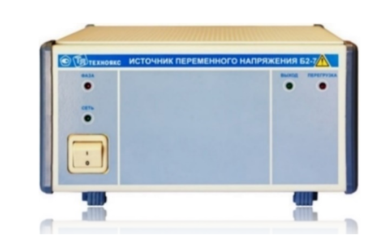
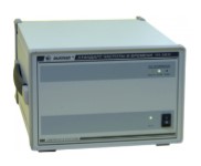
AC voltage source B2-7
The AC voltage source B2-7 is intended to provide devices and equipment with a stabilized AC voltage during the development, production, operation and repair of electronic devices.
Main properties:
Provides protection against overload and short circuits at the output.
Has a light indication:
- overload and short circuit protection tripping;
- incorrect connection of the power supply line to B2-7.
Technical specifications
The nominal value of the output voltage (SKZ) 220 V
The nominal value of the input and output voltage frequency is 50 Hz
Output electrical power, not less than 1000 VA
The main error in setting the output voltage is ± 2.2 V
Additional error in setting the output voltage caused by a deviation of the input voltage by ± 10% from the nominal value of 220 V ± 1.0 V
Additional error in setting the output voltage caused by a change in the load current from the maximum value to zero ± 2.0 V
Instability of the output voltage for any 10 minutes during 8 hours of continuous operation, no more than ± 2.0 V
Operating temperature range from -10 to 50 °C
AC power supply 220 V, 50 Hz
Power consumption, no more than 1200 VA
Overall dimensions, mm 240x128x349
Weight, not more than 6.5 kg
TEKHNOYAKS
Moscow
Produced in: Moscow
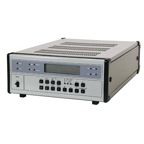
Frequency comparator CHK7-51
Mathematical processing of the measurement makes it possible to determine and display on the indicator board the relative systematic change in frequency, the average relative value of the frequency difference, the RMS relative frequency deviation, the RMS relative two-sample frequency deviation.
NNPO im. M.V.Frunze
Nizhny Novgorod
Produced in: Nizhny Novgorod
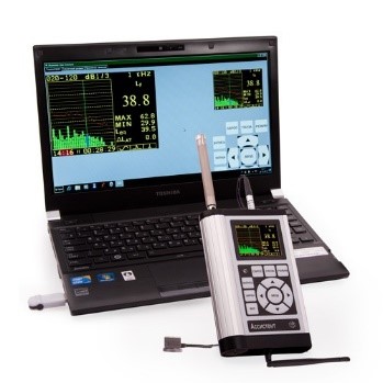
AWP (automated workplace) for measuring noise and vibration
Automated workplace for measuring noise, vibration, processing results and registration of protocols. It is equipped with a laptop with a pre-installed set of programs.
NMT-ZASHCHITA
Moscow
Produced in: Moscow
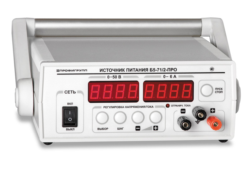
Pulse DC power supply B5-71/5-PRO
1 supp.
Regulated switching power supplies with highly stable output characteristics
Digital display of set and actual value, voltage and current (4 digits, LED)
Electronic load switching on/off
Protection against overload, short circuit, overheating and reverse polarity
Low ripple output voltage less than 2mV
Low ripple output current less than 5mA
Minimum discreteness of setting output voltage and current 0.007/0.005
Operating modes: stabilization U and I, dynamic load
RS-232 interface
DIPAUL
Saint Petersburg
Produced in: Saint Petersburg