Catalog
Search
210 products
View:
- Selected: 1Areas of use
- Selected: 0Item names
- Selected: 0Manufacturer
- Selected: 0Made in
- Selected: 0Additional
View:
210 products
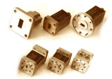
UCHX2-37
Basic properties:
Wide frequency range;
Sufficiently large output power;
High level of suppression of side harmonics of the input signal;
Low value of phase noise;
Relatively simple technical solutions:
- synchronization and frequency stabilization,
- stabilization and adjustment of the output power level,
- implementation of amplitude and frequency modulation modes;
Do not require external bias diodes.
Operating conditions:
Operating temperature range from minus 10 to 50 ° C;
The relative humidity of the air is up to 98% at a temperature of 25 ° C.
Technical characteristics
Input/output frequency range, GHz 12,93-18,75 / 25,86-37,5
Losses (max.), dB 13
Input power level, dBm 15-21
Unevenness of output power (Rvh. = 20 dBm), dB ± 1.5
The level of parasitic harmonics of the input signal at the output (min.), dBn 20
Output VSWR (max.) 2.0
Connector type:
• Input Coax. 3.5/1.5 mm (socket)
• Output Waveguide 7.2x3.4 mm
Overall dimensions, mm 29x24x24
Weight, g 60
TEKHNOYAKS
Moscow
Produced in: Moscow
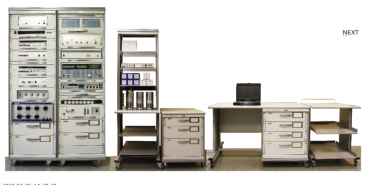
Verification module PM-9
The composition of the PM-9 calibration module:
Universal voltmeter calibrator H4-12 (2 pcs.);
Variable voltage calibrator H5-5A;
A measure of the stress ratio H4-8;
AC voltage voltmeter VK3-78A;
Generator-calibrator of harmonic signals SK6-122;
The meter-calibrator of the harmonic coefficient SK6-20A;
AC power source B2-7 (2 pcs.);
The measure of DC electrical resistance is multi-valued MS3070-2;
The measure of DC electrical resistance is multi-valued MS3055;
Decadal high-resistance resistance magazine M-109R;
Single-digit electrical resistance measures MS3080 (0.001; 0.01; 0.1 ohms);
Electrical resistance measures unambiguous MS3050M (1, 10, 100, 1000, 10000, 100000 Om);
The measure of electrical resistance is unambiguous P4013;
The measure of electrical resistance is unambiguous P4023;
The measure of electrical resistance is unambiguous P4033;
PC, printer;
Basic load-bearing structures (BNC).
Technical specifications
Measuring ranges of electrical quantities:
Constant electrical voltage DC from 1 MV to 1000 V
AC alternating electric voltage in the frequency range of 10 Hz ... 1 MHz from 10 mV to 1000 V
Alternating electric voltage high-frequency VRF in the frequency range of 10 Hz ... 2000 MHz from 10 mV to 100 V
Harmonic coefficient in the frequency range of 10 Hz ... 200 kHz from 0.001 to 100 %
Ranges of reproduction of electrical quantities:
Constant electrical voltage DC from 1 nV to 1000 V
AC alternating electric voltage in the frequency range of 10 Hz ... 1 MHz from 3 MV to 1000 V
Alternating electric voltage high-frequency VRF in the frequency range of 1 MHz ... 2000 MHz from 3 MV to 3 V
DC electric current from 1 µA to 20 A
The power of alternating electric current in the frequency range from 0.1 Hz to 10 kHz from 1 µA to 20 A
Electrical resistance from 0.001 ohms to 11
ohms Harmonic coefficient in the frequency range from 10 Hz to 200 kHz from 0.001 to 100 %
Measurement errors of electrical quantities:
Constant electrical voltage DC ± (0.0011 ... 4.0) %
AC alternating electric voltage, in the frequency range 10 Hz ... 1 MHz ± (0.0055 ... 1.2) %
Alternating electric voltage high-frequency VRF in the frequency range 1 MHz ... 2000 MHz ± (0.2 ... 6.0) %
Harmonic coefficient in the frequency range from 10 Hz to 200 kHz ± (0.0008 ... 2.0) %
Errors in the reproduction of electrical quantities:
Constant electrical voltage DC ± (0.0011 ... 4.0) %
AC alternating electric voltage in the frequency range 10 Hz ... 1 MHz ± (0.0055 ... 4.0) %
Alternating electric voltage high-frequency VRF in the frequency range 1 MHz ... 2000 MHz ± (0.6 ... 10.0) %
DC power ± (0.0033 ... 0.5) %
The power of alternating electric current in the frequency range from 10 Hz to 10 kHz ± (0.055 ... 1.0) %
Electrical resistance ± (0.001 ... 1.0) %
Harmonic coefficient in the frequency range from 10 Hz to 200 kHz ± (0.006 ... 2.0) %
General technical characteristics:
The area occupied by the module is 6-12 m2
Weight, not more than 430 kg
Power supply voltage from 198 to 242 V with a frequency of (50 ± 0.5) Hz
Power consumption, no more than 2000 VA
TEKHNOYAKS
Moscow
Produced in: Moscow
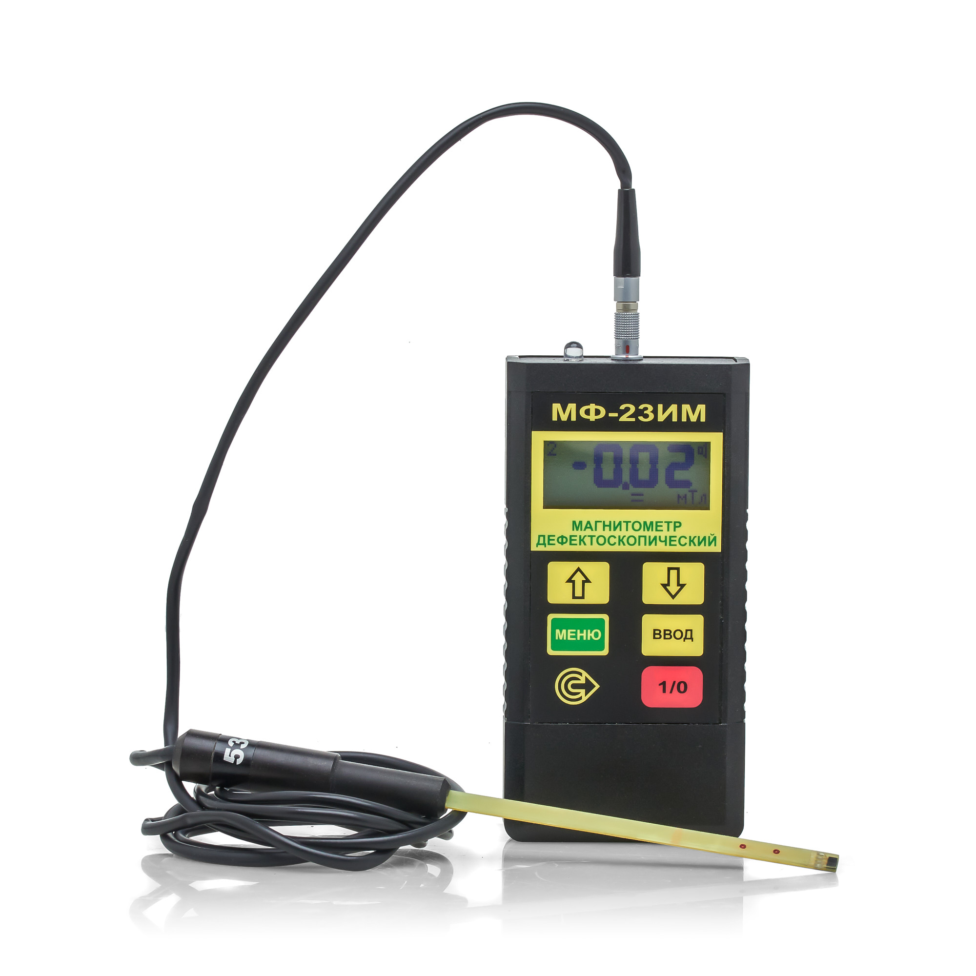
MF-23IM Flaw detection magnetometer
from
193 200 ₽
The MF-23IM flaw detection magnetometer allows you to determine the compliance of the ratio of the tangential and normal components of the magnetic field strength during magnetic particle testing using both the applied field method (AFM) and the remanent magnetization method (RMM) in accordance with the requirements of current regulatory documentation.
The MF-23IM flaw detection magnetometer meets the requirements in the field of non-destructive testing for the main industries: nuclear, energy, oil and gas complex, general and special engineering, railway transport, aerospace industry, elevator and crane facilities.
The flaw detection magnetometer is included in the State Register of Measuring Instruments (GRSI) under No. 20106-00. The magnetometer (milliteslameter) is also included in the register of measuring instruments, testing equipment and measurement methods used at JSC Russian Railways. The flaw detection magnetometer MF-23IM from the manufacturer is used to measure the parameters of constant, variable (industrial frequency) and pulsed magnetic fields when testing ferromagnetic products using the magnetic particle method, as well as to control the level of industrial interference. Specifications.
Magnetic field induction (strength) measurement range: - constant and variable (amplitude and average values) 0.5…1000 mT (4…8000 A/cm) - pulsed (amplitude value) 2…1000 mT (18…8000 A/cm) Indication of measurement results digital or digital + graphic Indicator liquid crystal display Power supply from 1 PP3 battery Current consumption, mA, no more than 15 Memory capacity for storing results 4080 Communication with a computer via infrared channel Dimensions of the electronic unit, mm, no more than 120x60x25 Weight of the electronic unit with battery, g 150
The minimum dimensions of the Hall transducer for the MF-23IM magnetometer make it possible to measure the induction and magnetic field strength in grooves, grooves, corner transitions, i.e. in those areas of the controlled product that are stress concentrators and the most dangerous from the point of view of crack formation; · Measurement of pulsed magnetizing field with pulse duration from 0.5 ms; · Small measurement error (see technical specifications table) · Compact size and low power consumption;
· The magnetometer has 2 modes for displaying measurement results – digital and graphic). The MF-23IM magnetometer in graphical display mode allows you to detect a demagnetizing pulse by displaying its shape and amplitude on a graphic display, as a result of which changes can be made to the magnetization circuit in a timely manner. · The software of the MF-23IM magnetometer allows you to flexibly configure not only the response thresholds, but also the time base, which allows you to tune out false indications caused by reverse emissions of the magnetic field or electromagnetic interference from operating power equipment (magnetizing devices or magnetic particle flaw detectors).
· Determination of the effective magnetization region, within which the tangential component of the magnetic field strength is sufficient for magnetic particle testing, and the ratio of the normal and tangential components of the magnetic field strength is less than or equal to 3. · Checking the mode of magnetization/demagnetization of test objects for compliance with the methodology/technological instructions for magnetic particle testing for a given object.
BASIC SET: Electronic unit Converter 1 Converter 2 Caliber PP3 battery CD with program Case Flaw detection magnetometer MF-23IM. Passport
RII MNPO SPEKTR
Moscow
Produced in: Moscow
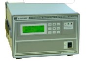
Rubidium frequency and time standards H1-1011
The modular construction principle makes it easy to adapt the devices to the specific requirements of the consumer. The standards are available in four versions – H1-1011, H1-1011/1, H1-1011/2 and H1-1011/3, which differ in metrological characteristics and a set of installed devices (modules). The built-in diagnostic system allows you to quickly determine the operability and condition of the main devices of the standards.
On the front panel of the devices H1-1011 and H1-1011/2 there is an LCD display and a control panel, with which you can quickly receive information about the current parameters of the devices included in the devices and adjust the frequency of the output signals.
The H1-1011 and H1-1011/2 standards can receive chronometric information from GLONASS and GPS satellite radio navigation systems and use it to synchronize the local time scale and automatically adjust the actual frequency value of the built-in highly stable rubidium frequency standard.
The composition of the standards H1-1011 and H1-1011/2 includes:
rubidium frequency standard H1-1014;
MPR-01 satellite radio navigation systems receiver module;
amplifier module for highly stable sinusoidal signals (at the customer's choice):
MUS-01 (3 independent outputs 10 MHz, connector type SR-50-73FV);
MUS-02 (3 independent outputs of 5 MHz, connector type SR-50-73FV);
MUS-03 (3 independent outputs of 1, 5 and 10 MHz, connector type SR-50-73FV);
MUS-04 (6 independent outputs of 1, 5 and 10 MHz in any combination at the customer's choice, SMA connector type);
MS synthesizer module with software (SMA connector type) instead of an amplifier module (at the customer's request).
The scope of delivery (at the request of the customer) includes an antenna for the SRNS receiver as part of:
antenna unit;
mounting device;
antenna cable (maximum length 60 m).
The H1-1011/1 and H1-1011/3 standards include:
the rubidium frequency standard H1-1013;
two modules of amplifiers of highly stable sinusoidal signals (at the customer's choice):
MUS-01 (3 independent outputs 10 MHz, connector type SR-50-73FV);
MUS-02 (3 independent outputs of 5 MHz, connector type SR-50-73FV);
MUS-03 (3 independent outputs of 1, 5 and 10 MHz, connector type SR-50-73FV);
MUS-04 (6 independent outputs of 1, 5 and 10 MHz in any combination at the customer's choice, SMA connector type);
MS synthesizer module with software (SMA connector type) instead of an amplifier module (at the customer's request).
Ruknar
Nizhny Novgorod
Produced in: Nizhny Novgorod

Low-frequency signal generator G3-131A
Technical specifications:
The waveform is sinusoidal, rectangular (TTL)
Frequency range from 2 Hz to 2 MHz
Frequency setting error ±0.05%
Frequency instability ±0.02% in 15 min
Signal amplitude ±5 V at 600 ohm load
±10 V without load
Limits for adjusting the output signal level from 1 mV to 3.75 V (scr) at a load of 600 ohms
from 2 mV to 7.5 V (scz) without load
Signal level unevenness ± 2% at frequencies from 20 Hz to 200 kHz
relative to 1 kHz ± 5% at frequencies from 200 kHz to 2 MHz
Harmonic coefficient ± 0.3% at frequencies from 2 to 20 Hz
± 0.2% at frequencies from 20 Hz to 100 kHz
±1% at frequencies from 100 kHz to 2 MHz
Parameters of the rectangular (TTL) signal form log. "1" 3 2.4 V; log. "0" ≤ 0.4 V the
duration of the front, the cutoff is not more than 100 ns
Operating temperature range from minus 10 °C to + 40 °C
Power supply ~230 V, 50 Hz; 10 V×A
Dimensions; weight 210×71×255 mm; 2
MNIPI
Minsk
Produced in: Belarus, Minsk
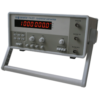
Generators G4-221, G4-221/1
Technical specifications:
Frequency range of sinusoidal waveforms, 0.1 Hz - 17 MHz
Frequency range of rectangular-shaped signals, 0.1 Hz - 1 MHz
Frequency setting discreteness, ±(0.012 + 0.0001 f), f in Hz
Frequency instability in 15 minutes, no more than ± 1•10-5
Smooth signal attenuation, 40 dB
Stepwise signal attenuation, 20, 40, 60 dB
MNIPI
Minsk
Produced in: Belarus, Minsk
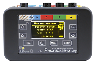
8-CHANNEL PORTABLE RECORDER OF EMERGENCY AND NORMAL MODES PARMA RAS VAF-A(M2)
It will help relay protection and automation services, the chief power engineer of industrial enterprises and a wide range of specialists engaged in setting up, monitoring, diagnostics and operation of electrical installations to solve the following tasks:
− record emergency waveforms on 4 current channels and 4 voltage channels, with data stored in COMTRADE format
- take daily load schedules and carry out long−term monitoring of the parameters of the power grid (recorder)
- to monitor the conduct of switching in switchgear
− identify the causes of the emergency mode
− to evaluate the correctness of the operation of the RSiA and PA devices
− determine the harmonic composition of current and voltage (up to and including the 14th harmonic)
− control phase alternation
− remove the voltage characteristics
− measure the phase shift angle and perform the construction of vector diagrams of voltage and current
− control the circuits in the SHPT
− check the integrity of electrical conductors (ringing)
− carry out maintenance of relay protection circuits and power circuits of electrical installations
− monitor the status and diagnostics of DC circuits
PARMA
Saint Petersburg
Produced in: Saint Petersburg
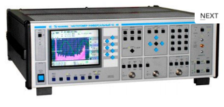
Universal frequency meter Ch3-89
The frequency meter is able to work both independently and as part of automated measuring systems with interfaces such as USB or RS-232.
Technical specifications
Frequency and period of sinusoidal signals (inputs A, B) 0.001 Hz - 150 MHz
Frequency of video pulse signals (inputs A, B) 0.001 Hz - 100 MHz
Frequency of continuous sinusoidal oscillations (input C) (0.1 - 1) GHz
Frequency of continuous sinusoidal oscillations (input D) (1 - 37.5) GHz
Carrier frequency of a continuous signal with frequency modulation (FM) (input D) Fh = (1 - 18) GHz, Fm = 100 Hz-100 kHz; frequency deviation from 10 kHz to 10 MHz
Carrier frequency of a continuous signal with amplitude modulation (AM) (input D) Fh = (1 - 18) GHz, Fm = 100 Hz - 100 kHz; AM factor up to 100%
Carrier frequency of a continuous radio pulse sequence (IM) signal (input D) Fn = (1-37.5) GHz, from 0.15 microseconds to 1ms, Fsl from 100 Hz to 3 MHz, from 2 to 103
Pulse duration 10 ns – 0.1 s
Time interval from -10 to 10 s
The duration of the front, the decay of the pulses is 5 ns - 100 microseconds
Phase difference of two synchronous sinusoidal signals from minus 360° to 360°
The measurement error of the phase difference of two synchronous sinusoidal signals is ± 0.36° (from 1 kHz to 1 MHz) ± 3.6° (above 1 MHz)
Input signal level:
•for sinusoidal signal (inputs A, B) (0.03 - 7.0) V
•for video pulse signal (inputs A, B) (0.1 - 10.0) V
•for a sinusoidal signal (input C) (0.03 - 1.0) V
•for sinusoidal and IM signals (input D) 10 MW (from 1 to 8 GHz); 40 MW (sv. 8 to 18 GHz); 50 MW (sv. 18 to 37.5 GHz).
The nominal frequency value of the reference quartz oscillator is 10 MHz
Relative error in the frequency of the quartz oscillator, no more than ± 2x10⁻⁷ in 12 months
Operating temperature range from 5 to 40 °C
AC power supply 220 V, 50 Hz
Power consumption, no more than 100 VhA
Overall dimensions, mm 496x174x459
Weight, not more than 16 kg
TEKHNOYAKS
Moscow
Produced in: Moscow
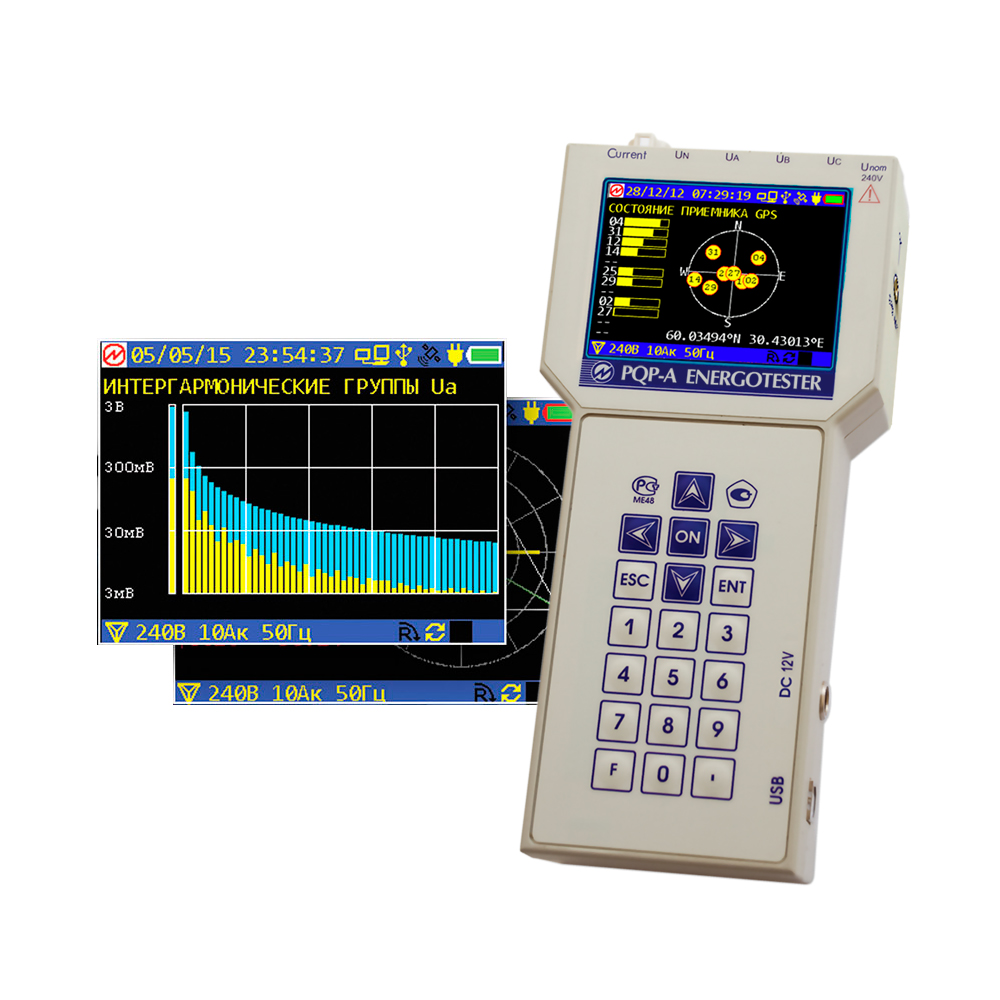
PKE-A Energy Tester
The devices are designed for:
measurements and registration of the main indicators of the quality of electrical energy established by GOST 32144-2013 (GOST R 54149-2010) with registration of protocols according to GOST 33073-2014;
measurements and registration of the main parameters of electrical energy in single-phase and three-phase electrical networks (including the effective values of voltages and currents with sinusoidal and distorted curves; active, reactive and full electrical power);
measurements of parameters of secondary circuits (load capacity of measuring transformers and voltage drop) in electric energy metering systems and electric energy losses in power supply lines.
functional test and verification of connection of meters of active and reactive power and energy, energy measuring converters of voltage, current at the places of their operation;
functional test and verification of the connection of single-phase and three-phase electric energy meters without breaking current circuits to detect theft of electricity;
measurements of electricity losses in the power supply line.
The PKE-A energy tester provides registration with subsequent transfer to a personal computer (PC) of statistical data on the PKE:
Values of the PCE according to GOST 30804.4.30 (GOST P 51317.4.30) and GOST 30804.4.7 (GOST P 51317.4.7) with a registration depth of 512 days;
Values and durations of voltage dips and overvoltages;
Values of the short-term dose of flicker;
Parameters of the electrical network and vector diagrams with the depth of registration:
- 24 hours for averaging time of 3 s,
- 200 days for averaging time of 10 min.
The program "Energy Monitoring ES" provides the formation of quality control protocols in the form of GOST 33073-2014.
Marsenergo
Saint Petersburg
Produced in: Saint Petersburg
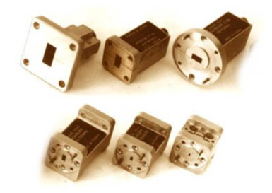
UCHX3-53
Basic properties:
Wide frequency range;
Sufficiently large output power;
High level of suppression of side harmonics of the input signal;
Low phase noise value;
Relatively simple technical solutions:
- synchronization and frequency stabilization,
- stabilization and adjustment of the output power level,
- implementation of amplitude and frequency modulation modes;
Do not require external bias diodes.
Operating conditions:
Operating temperature range from minus 10 to 50 °C;
The relative humidity of the air is up to 98% at a temperature of 25 ° C.
Technical characteristics
Input/output frequency range, GHz 12,50- 17,86 / 37,50- 53,57
Losses (max.), dB 17
Input power level, 15-20 dBm
Unevenness of output power (Rvh. = 20 dBm), dB ± 2.0
The level of parasitic harmonics of the input signal at the output (min.), dBn 20
Output VSWR (max.) 2.0
Connector type:
• Input Coax. 3.5/1.5 mm (socket)
• Output Waveguide 5,2x2,6 mm
Overall dimensions, mm 34x20x20
Weight, g 60
TEKHNOYAKS
Moscow
Produced in: Moscow
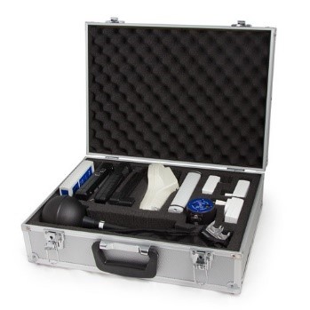
KOMBI-04
from
380 000 ₽
A set for measuring the parameters of the microclimate, the index of the thermal load of the medium (TNS), thermal radiation, light environment, UV radiation, laser radiation
NMT-ZASHCHITA
Moscow
Produced in: Moscow
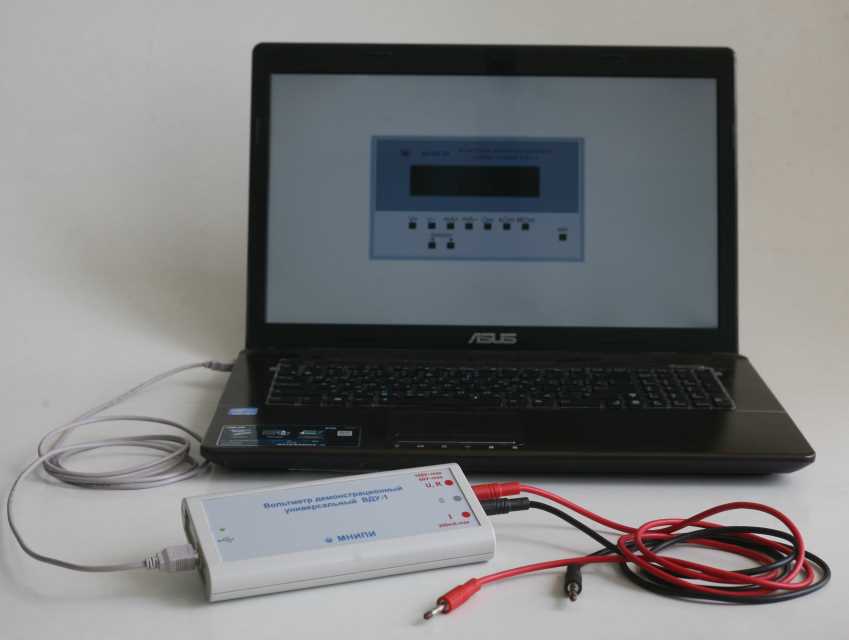
Voltmeter demonstration universal VDU-1
Designed to measure electrical quantities (DC voltage and strength, AC voltage and strength, DC electrical resistance) during demonstration work in physics. The device performs the function of a demonstration multimeter.
Technical specifications:
Measurement of DC voltage from 0 to 100 V
measurement error, not more than 1.0 %
Measurement of AC voltage from 0 to 60 V
measurement error, not more than 1.0%
measurement of DC power from 0.01 to 200
measurement error, not more than 1.0 %
Measurement of AC power from 0.01 to 200 mA
measurement error, not more than 1.0 %
Measurement of DC resistance from 1 ohm to 2 mOhm
measurement error, no more than 1.0%
power supply from the USB port of the computer
power consumption, no more than 0.6 V × A
weight, no more than 0.3 kg
overall dimensions 172x25x77 mm
MNIPI
Minsk
Produced in: Belarus, Minsk