Catalog
Search
189 products
View:
- Selected: 1Areas of use
- Selected: 0Item names
- Selected: 0Manufacturer
- Selected: 0Made in
- Selected: 0Additional
View:
189 products

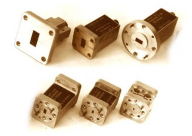
VD-7.2×3.4
A flexible waveguide is a piece of high-quality dielectric, which ends with transitions to standard waveguides with flanges.
For ease of operation, the waveguide is protected by an elastic shell.
Basic properties
Manufacturability of the connection;
Small losses and VSWR;
Economy.
Operating conditions
Operating temperature range from 5 to 50 ° C;
The relative humidity of the air is up to 98% at a temperature of 25 ° C.
Technical specifications
Waveguide cross section, mm 7.2×3.4
Flange type according to GOST RV 51914-2002
Frequency range, GHz 25.95-37.50
VSWR 1.25
Losses, dB 2.0
Length, mm* 500
TEKHNOYAKS
Moscow
Produced in: Moscow
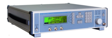
High-frequency signal generator G4-230
The generator is capable of operating both autonomously and as part of automated measuring systems with USB and IEEE-488 (CPC) interfaces.
Technical specifications
Frequency range from 5 to 17.85 GHz
Frequency tuning discreteness 0.001 Hz
The main error of the frequency setting is ± 3x10⁻⁷ Hz
The range of setting the output signal power level at the main output is from minus 110 to 13 dBm
The basic error of setting the reference power level is ± 1.0 dB
Instability of the output signal power level for any 15-minute time interval of no more than 0.1 dB
Metrological characteristics of the generator in the FM operation mode:
- frequency range of the modulating signal:
low frequency from 1 Hz to 20 kHz
RFM from 10 to 100 kHz
- frequency deviation setting range (taking into account the carrier frequency value):
low frequency from 1 Hz to 100 kHz
RFM from 50 to 10000 kHz
- the main error of the frequency deviation setting is ± (3 – 18)%
Metrological characteristics of the generator in AM operation mode:
- frequency range of the modulating signal from 0.05 to 5.0 kHz
- the range of setting the amplitude modulation coefficient from 1 to 50 %
- the main error in setting the amplitude modulation coefficient:
Internal ± (0.15M + 0.2)%
External ± (0.20M + 0.5)%
Metrological characteristics of the generator in the IM operation mode:
- the duration range of modulating pulses from 100 ns to 20 s
- the range of the modulating pulse repetition period from 140 ns to 30 s
- the difference in the duration of the output RF pulses from the duration of the modulating pulses ± 100 ns
Operating temperature range from minus 10 to 40 °C
AC power supply 220 V, 50 Hz
Power consumption, no more than 150 VA
Overall dimensions, mm 498x136x487
Weight, not more than 15 kg
TEKHNOYAKS
Moscow
Produced in: Moscow
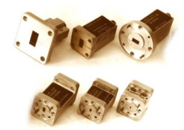
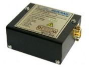
UCHX2-37
Basic properties:
Wide frequency range;
Sufficiently large output power;
High level of suppression of side harmonics of the input signal;
Low value of phase noise;
Relatively simple technical solutions:
- synchronization and frequency stabilization,
- stabilization and adjustment of the output power level,
- implementation of amplitude and frequency modulation modes;
Do not require external bias diodes.
Operating conditions:
Operating temperature range from minus 10 to 50 ° C;
The relative humidity of the air is up to 98% at a temperature of 25 ° C.
Technical characteristics
Input/output frequency range, GHz 12,93-18,75 / 25,86-37,5
Losses (max.), dB 13
Input power level, dBm 15-21
Unevenness of output power (Rvh. = 20 dBm), dB ± 1.5
The level of parasitic harmonics of the input signal at the output (min.), dBn 20
Output VSWR (max.) 2.0
Connector type:
• Input Coax. 3.5/1.5 mm (socket)
• Output Waveguide 7.2x3.4 mm
Overall dimensions, mm 29x24x24
Weight, g 60
TEKHNOYAKS
Moscow
Produced in: Moscow
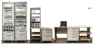
Verification module PM-9
The composition of the PM-9 calibration module:
Universal voltmeter calibrator H4-12 (2 pcs.);
Variable voltage calibrator H5-5A;
A measure of the stress ratio H4-8;
AC voltage voltmeter VK3-78A;
Generator-calibrator of harmonic signals SK6-122;
The meter-calibrator of the harmonic coefficient SK6-20A;
AC power source B2-7 (2 pcs.);
The measure of DC electrical resistance is multi-valued MS3070-2;
The measure of DC electrical resistance is multi-valued MS3055;
Decadal high-resistance resistance magazine M-109R;
Single-digit electrical resistance measures MS3080 (0.001; 0.01; 0.1 ohms);
Electrical resistance measures unambiguous MS3050M (1, 10, 100, 1000, 10000, 100000 Om);
The measure of electrical resistance is unambiguous P4013;
The measure of electrical resistance is unambiguous P4023;
The measure of electrical resistance is unambiguous P4033;
PC, printer;
Basic load-bearing structures (BNC).
Technical specifications
Measuring ranges of electrical quantities:
Constant electrical voltage DC from 1 MV to 1000 V
AC alternating electric voltage in the frequency range of 10 Hz ... 1 MHz from 10 mV to 1000 V
Alternating electric voltage high-frequency VRF in the frequency range of 10 Hz ... 2000 MHz from 10 mV to 100 V
Harmonic coefficient in the frequency range of 10 Hz ... 200 kHz from 0.001 to 100 %
Ranges of reproduction of electrical quantities:
Constant electrical voltage DC from 1 nV to 1000 V
AC alternating electric voltage in the frequency range of 10 Hz ... 1 MHz from 3 MV to 1000 V
Alternating electric voltage high-frequency VRF in the frequency range of 1 MHz ... 2000 MHz from 3 MV to 3 V
DC electric current from 1 µA to 20 A
The power of alternating electric current in the frequency range from 0.1 Hz to 10 kHz from 1 µA to 20 A
Electrical resistance from 0.001 ohms to 11
ohms Harmonic coefficient in the frequency range from 10 Hz to 200 kHz from 0.001 to 100 %
Measurement errors of electrical quantities:
Constant electrical voltage DC ± (0.0011 ... 4.0) %
AC alternating electric voltage, in the frequency range 10 Hz ... 1 MHz ± (0.0055 ... 1.2) %
Alternating electric voltage high-frequency VRF in the frequency range 1 MHz ... 2000 MHz ± (0.2 ... 6.0) %
Harmonic coefficient in the frequency range from 10 Hz to 200 kHz ± (0.0008 ... 2.0) %
Errors in the reproduction of electrical quantities:
Constant electrical voltage DC ± (0.0011 ... 4.0) %
AC alternating electric voltage in the frequency range 10 Hz ... 1 MHz ± (0.0055 ... 4.0) %
Alternating electric voltage high-frequency VRF in the frequency range 1 MHz ... 2000 MHz ± (0.6 ... 10.0) %
DC power ± (0.0033 ... 0.5) %
The power of alternating electric current in the frequency range from 10 Hz to 10 kHz ± (0.055 ... 1.0) %
Electrical resistance ± (0.001 ... 1.0) %
Harmonic coefficient in the frequency range from 10 Hz to 200 kHz ± (0.006 ... 2.0) %
General technical characteristics:
The area occupied by the module is 6-12 m2
Weight, not more than 430 kg
Power supply voltage from 198 to 242 V with a frequency of (50 ± 0.5) Hz
Power consumption, no more than 2000 VA
TEKHNOYAKS
Moscow
Produced in: Moscow
Rubidium frequency and time standards H1-1011
The modular construction principle makes it easy to adapt the devices to the specific requirements of the consumer. The standards are available in four versions – H1-1011, H1-1011/1, H1-1011/2 and H1-1011/3, which differ in metrological characteristics and a set of installed devices (modules). The built-in diagnostic system allows you to quickly determine the operability and condition of the main devices of the standards.
On the front panel of the devices H1-1011 and H1-1011/2 there is an LCD display and a control panel, with which you can quickly receive information about the current parameters of the devices included in the devices and adjust the frequency of the output signals.
The H1-1011 and H1-1011/2 standards can receive chronometric information from GLONASS and GPS satellite radio navigation systems and use it to synchronize the local time scale and automatically adjust the actual frequency value of the built-in highly stable rubidium frequency standard.
The composition of the standards H1-1011 and H1-1011/2 includes:
rubidium frequency standard H1-1014;
MPR-01 satellite radio navigation systems receiver module;
amplifier module for highly stable sinusoidal signals (at the customer's choice):
MUS-01 (3 independent outputs 10 MHz, connector type SR-50-73FV);
MUS-02 (3 independent outputs of 5 MHz, connector type SR-50-73FV);
MUS-03 (3 independent outputs of 1, 5 and 10 MHz, connector type SR-50-73FV);
MUS-04 (6 independent outputs of 1, 5 and 10 MHz in any combination at the customer's choice, SMA connector type);
MS synthesizer module with software (SMA connector type) instead of an amplifier module (at the customer's request).
The scope of delivery (at the request of the customer) includes an antenna for the SRNS receiver as part of:
antenna unit;
mounting device;
antenna cable (maximum length 60 m).
The H1-1011/1 and H1-1011/3 standards include:
the rubidium frequency standard H1-1013;
two modules of amplifiers of highly stable sinusoidal signals (at the customer's choice):
MUS-01 (3 independent outputs 10 MHz, connector type SR-50-73FV);
MUS-02 (3 independent outputs of 5 MHz, connector type SR-50-73FV);
MUS-03 (3 independent outputs of 1, 5 and 10 MHz, connector type SR-50-73FV);
MUS-04 (6 independent outputs of 1, 5 and 10 MHz in any combination at the customer's choice, SMA connector type);
MS synthesizer module with software (SMA connector type) instead of an amplifier module (at the customer's request).
Ruknar
Nizhny Novgorod
Produced in: Nizhny Novgorod

Low-frequency signal generator G3-131A
Technical specifications:
The waveform is sinusoidal, rectangular (TTL)
Frequency range from 2 Hz to 2 MHz
Frequency setting error ±0.05%
Frequency instability ±0.02% in 15 min
Signal amplitude ±5 V at 600 ohm load
±10 V without load
Limits for adjusting the output signal level from 1 mV to 3.75 V (scr) at a load of 600 ohms
from 2 mV to 7.5 V (scz) without load
Signal level unevenness ± 2% at frequencies from 20 Hz to 200 kHz
relative to 1 kHz ± 5% at frequencies from 200 kHz to 2 MHz
Harmonic coefficient ± 0.3% at frequencies from 2 to 20 Hz
± 0.2% at frequencies from 20 Hz to 100 kHz
±1% at frequencies from 100 kHz to 2 MHz
Parameters of the rectangular (TTL) signal form log. "1" 3 2.4 V; log. "0" ≤ 0.4 V the
duration of the front, the cutoff is not more than 100 ns
Operating temperature range from minus 10 °C to + 40 °C
Power supply ~230 V, 50 Hz; 10 V×A
Dimensions; weight 210×71×255 mm; 2
MNIPI
Minsk
Produced in: Belarus, Minsk
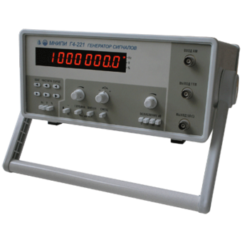
Generators G4-221, G4-221/1
Technical specifications:
Frequency range of sinusoidal waveforms, 0.1 Hz - 17 MHz
Frequency range of rectangular-shaped signals, 0.1 Hz - 1 MHz
Frequency setting discreteness, ±(0.012 + 0.0001 f), f in Hz
Frequency instability in 15 minutes, no more than ± 1•10-5
Smooth signal attenuation, 40 dB
Stepwise signal attenuation, 20, 40, 60 dB
MNIPI
Minsk
Produced in: Belarus, Minsk
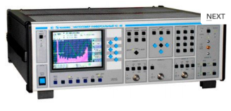
Universal frequency meter Ch3-89
The frequency meter is able to work both independently and as part of automated measuring systems with interfaces such as USB or RS-232.
Technical specifications
Frequency and period of sinusoidal signals (inputs A, B) 0.001 Hz - 150 MHz
Frequency of video pulse signals (inputs A, B) 0.001 Hz - 100 MHz
Frequency of continuous sinusoidal oscillations (input C) (0.1 - 1) GHz
Frequency of continuous sinusoidal oscillations (input D) (1 - 37.5) GHz
Carrier frequency of a continuous signal with frequency modulation (FM) (input D) Fh = (1 - 18) GHz, Fm = 100 Hz-100 kHz; frequency deviation from 10 kHz to 10 MHz
Carrier frequency of a continuous signal with amplitude modulation (AM) (input D) Fh = (1 - 18) GHz, Fm = 100 Hz - 100 kHz; AM factor up to 100%
Carrier frequency of a continuous radio pulse sequence (IM) signal (input D) Fn = (1-37.5) GHz, from 0.15 microseconds to 1ms, Fsl from 100 Hz to 3 MHz, from 2 to 103
Pulse duration 10 ns – 0.1 s
Time interval from -10 to 10 s
The duration of the front, the decay of the pulses is 5 ns - 100 microseconds
Phase difference of two synchronous sinusoidal signals from minus 360° to 360°
The measurement error of the phase difference of two synchronous sinusoidal signals is ± 0.36° (from 1 kHz to 1 MHz) ± 3.6° (above 1 MHz)
Input signal level:
•for sinusoidal signal (inputs A, B) (0.03 - 7.0) V
•for video pulse signal (inputs A, B) (0.1 - 10.0) V
•for a sinusoidal signal (input C) (0.03 - 1.0) V
•for sinusoidal and IM signals (input D) 10 MW (from 1 to 8 GHz); 40 MW (sv. 8 to 18 GHz); 50 MW (sv. 18 to 37.5 GHz).
The nominal frequency value of the reference quartz oscillator is 10 MHz
Relative error in the frequency of the quartz oscillator, no more than ± 2x10⁻⁷ in 12 months
Operating temperature range from 5 to 40 °C
AC power supply 220 V, 50 Hz
Power consumption, no more than 100 VhA
Overall dimensions, mm 496x174x459
Weight, not more than 16 kg
TEKHNOYAKS
Moscow
Produced in: Moscow
UCHX3-53
Basic properties:
Wide frequency range;
Sufficiently large output power;
High level of suppression of side harmonics of the input signal;
Low phase noise value;
Relatively simple technical solutions:
- synchronization and frequency stabilization,
- stabilization and adjustment of the output power level,
- implementation of amplitude and frequency modulation modes;
Do not require external bias diodes.
Operating conditions:
Operating temperature range from minus 10 to 50 °C;
The relative humidity of the air is up to 98% at a temperature of 25 ° C.
Technical characteristics
Input/output frequency range, GHz 12,50- 17,86 / 37,50- 53,57
Losses (max.), dB 17
Input power level, 15-20 dBm
Unevenness of output power (Rvh. = 20 dBm), dB ± 2.0
The level of parasitic harmonics of the input signal at the output (min.), dBn 20
Output VSWR (max.) 2.0
Connector type:
• Input Coax. 3.5/1.5 mm (socket)
• Output Waveguide 5,2x2,6 mm
Overall dimensions, mm 34x20x20
Weight, g 60
TEKHNOYAKS
Moscow
Produced in: Moscow
Rubidium frequency standard H1-1022
Rubidium frequency standards H1-1022 are available both in the standard version and with various options that have differences in functionality and technical characteristics:
option 01 is a device with high short–term stability of the output signal frequency;
option 02 – a device with a low-level phase noise in the output signal spectrum;
option 03 – the device has a binding module in its composition, which allows automatic correction of the frequency of the output signal according to the signal of the external time scale;
option 04 – the device has a synthesizer module in its composition, which allows you to receive a sinusoidal signal of a given frequency at the output of the device in the range from 100 Hz to 100 MHz in steps of the order of 4 × 10⁻⁶ Hz;
option 05 is a device with an extended range of ambient operating temperatures.
Through the built-in RS-232 interface, telemetry information is collected from the device nodes, and commands to change the frequency of the output signal are transmitted.
The H1-1022 frequency standards have no domestic analogues in terms of their small dimensions, weight, power consumption and operating time, as well as in terms of their numerous functional capabilities.
Ruknar
Nizhny Novgorod
Produced in: Nizhny Novgorod
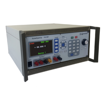
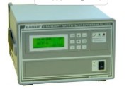
Universal calibrator H4-301
Technical specifications:
Voltage reproduction range Uk 200 mV 0.07 + 0.01
DC: from 50 MV to 600 V, Uk 2 V 0.05 + 0.005
sub-bands (Uk) 200 mV; 2; 20; 200; 600 V Uk 20 V 0.05 + 0.005
Basic error, ± (% of U + % of Uk): Uk 200 V 0.07 + 0.01
Uk 600 V 0.1 + 0.02
Voltage reproduction range UK 200 mV 0.2 + 0.05
AC: from 1 mV to 600 V, Uk 2; 20 V 0.15 + 0.02
sub-bands (Uk) 200 mV; 2; 20; 200; 600 V from 20 Hz to 20 kHz
Basic error, ± (% of U + % of Uk): sv. 20 to 40 kHz 0.2 + 0.1
Uk 200 V; 600 V:
from 40 Hz to 1 kHz 0.2 + 0.05
Power reproduction range Ik 200 Ma 0.1 + 0.02
DC: from 1 Ma to 5 A, Ik 2; 20; 200 mA 0.1 + 0.01
sub-bands (Ik) 200 Ma; 2; 20; 200 mA; 2; 5 A Ik 2 A; 5 A 0.1 + 0.02
Basic error, ± (% of I + % of Ic):
AC power reproduction range: from 10 Ma to 5 A
sub-bands (Ic) 200 Ma; 2; 20; 200 mA; 2; 5 A 0.15 + 0.05
Frequency range from 20 Hz to 1 kHz
Basic error, ± (% of I + % of Ic):
USB interface
Operating temperature range from minus 10 °C to + 50 °C
Dimensions; weight 420×342×184.5 mm; 10 kg
MNIPI
Minsk
Produced in: Belarus, Minsk
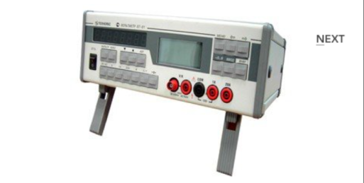
Universal voltmeter V7-81
The voltmeter is capable of operating both independently and as part of automated measuring systems with RS-232 type interfaces.
Technical specifications
Ranges of measurement of electrical quantities:
- constant electrical voltage from 10 MV to 1000 V
- SCR of alternating electric voltage in the frequency range from 10 Hz to 10 MHz (AC) from 1 mV to 750 V
- DC current from 0.1 µA to 20 A
- SCR of alternating electric current in the frequency range from 10 Hz to 5 kHz from 10 µA to 20 A
- electrical resistance from 10 mOhm to 1 GOm
- frequency of the measured alternating electric voltage from 10 Hz to 1 MHz
Measurement errors of electrical quantities:
- constant electrical voltage ± (0.0028 - 20)%
- SCR of alternating electric voltage in the frequency range from 10 Hz to 10 MHz (AC) ± (0.09 - 15)%
- DC power ± (0.012 - 20)%
- SCR of alternating electric current in the frequency range from 10 Hz to 5 kHz ± (0.11 - 2.35) %
- electrical resistance ± (0.007 - 5.5)%
- frequency of the measured alternating electric voltage ± (0.1 -10.1)%
General characteristics:
Operating temperature range from 5 to 40 °C
AC power supply 220 V, 50 Hz
Power consumption, no more than 20 VA
Overall dimensions, mm 291x110x308
Weight, not more than 4.5 kg
TEKHNOYAKS
Moscow
Produced in: Moscow