Language selection
В настоящее время портал работает - ведутся технические работы.
Catalog
Search
246 products
View:
- Selected: 1Areas of use
- Selected: 0Item names
- Selected: 0Manufacturer
- Selected: 0Made in
- Selected: 0Additional
View:
246 products
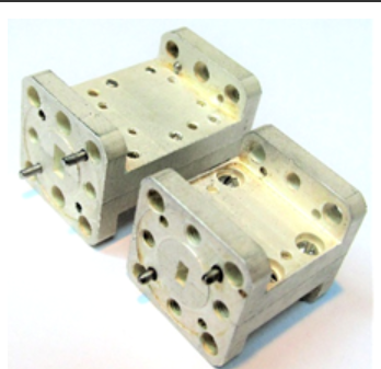
FNCH-78
Structurally, waveguide LPF 37-78 GHz are made on metal plates located in the center of the E-plane of the waveguide.
These LFS can be used in conjunction with waveguide bandpass filters to increase the suppression of spurious signals and expand the upper band of the barrier.
Basic properties
Low bandwidth losses;
A wide barrage strip.
Operating conditions
Operating temperature range from minus 10
up to 50 ° C;
The relative humidity of the air is up to 98% at a temperature of 25 ° C.
Technical specifications
Waveguide cross section, mm 3.6×1.8
Bandwidth Fh-Fb at the level of -1 dB, GHz 60-78
The barrier band at the level of -30 dB, GHz 85-120
Bandwidth loss, 0.5-1.2 dB
TEKHNOYAKS
Moscow
Produced in: Moscow
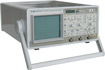
Oscilloscope S1-167/2
Designed for the study of periodic electrical signals by visual observation and measurement of their amplitude and time parameters on the scale of the CRT screen in the frequency band 0 - 25 MHz with a built-in multimeter measuring voltage and DC power, the average square value of voltage and AC power, DC electrical resistance.
Technical specifications:
Vertical deviation
Number of channels 2
Bandwidth 0-25 MHz
Deviation coefficients 2 mV/div-10 V/div (step 1-2-5)
Installation error ± 3%
Rise time of PH <= 14 nsec
Input impedance 1 mOhm/23 pF, with divider 1:10-10 mOhm/12 pF
with open input <=110 V
with closed input <=110 V
with divider 1:10 <= 250 V
range U post. U AC: 1 mV–500 V
Error 0.1% (U post); 0.3% -1% (U perem. 40 Hz–100 kHz)
Range I post., I AC.: 1 mA–2 A
Error: 0.25% (I post.); 0.5% (I perem. 40 Hz–5 kHz)
R Range: 1 Ohm–1 mOhm
Error R: 0.2%
3.5-digit indicator
Automatic selection of limits.
MNIPI
Minsk
Produced in: Belarus, Minsk
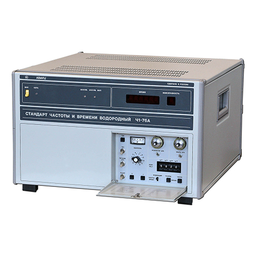
Frequency and time standard hydrogen Ch1-76A
NNPO im. M.V.Frunze
Nizhny Novgorod
Produced in: Nizhny Novgorod
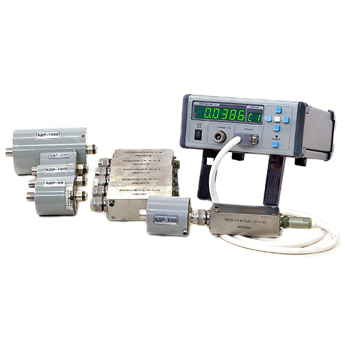
Rubidium frequency and time standards H1-1011/1
The modular construction principle makes it easy to adapt the devices to the specific requirements of the consumer. The standards are available in four versions – H1-1011, H1-1011/1, H1-1011/2 and H1-1011/3, which differ in metrological characteristics and a set of installed devices (modules). The built-in diagnostic system allows you to quickly determine the operability and condition of the main devices of the standards.
On the front panel of the devices H1-1011 and H1-1011/2 there is an LCD display and a control panel, with which you can quickly receive information about the current parameters of the devices included in the devices and adjust the frequency of the output signals.
The H1-1011 and H1-1011/2 standards can receive chronometric information from GLONASS and GPS satellite radio navigation systems and use it to synchronize the local time scale and automatically adjust the actual frequency value of the built-in highly stable rubidium frequency standard.
The H1-1011 and H1-1011/2 standards include:
rubidium frequency standard H1-1014;
MPR-01 satellite radio navigation systems receiver module;
amplifier module for highly stable sinusoidal signals (at the customer's choice):
MUS-01 (3 independent outputs 10 MHz, connector type SR-50-73FV);
MUS-02 (3 independent outputs of 5 MHz, connector type SR-50-73FV);
MUS-03 (3 independent outputs of 1, 5 and 10 MHz, connector type SR-50-73FV);
MUS-04 (6 independent outputs of 1, 5 and 10 MHz in any combination at the customer's choice, SMA connector type);
MS synthesizer module with software (SMA connector type) instead of an amplifier module (at the customer's request).
The scope of delivery (at the request of the customer) includes an antenna for the SRNS receiver as part of:
antenna unit;
mounting device;
antenna cable (maximum length 60 m).
The H1-1011/1 and H1-1011/3 standards include:
the rubidium frequency standard H1-1013;
two modules of amplifiers of highly stable sinusoidal signals (at the customer's choice):
MUS-01 (3 independent outputs 10 MHz, connector type SR-50-73FV);
MUS-02 (3 independent outputs of 5 MHz, connector type SR-50-73FV);
MUS-03 (3 independent outputs of 1, 5 and 10 MHz, connector type SR-50-73FV);
MUS-04 (6 independent outputs of 1, 5 and 10 MHz in any combination at the customer's choice, SMA connector type);
MS synthesizer module with software (SMA connector type) instead of an amplifier module (at the customer's request).
Ruknar
Nizhny Novgorod
Produced in: Nizhny Novgorod
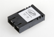
Optical Transceiver 1x9 OC3/STM1/Fast Ethernet (155Mbps)
Optical transceivers are available in 9-pin plastic cases with separate optical input/output for SC (FC) connectors
FTI-Optronik
Saint Petersburg
Produced in: Saint Petersburg
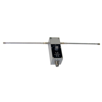
Measuring antenna P6-61
Technical specifications:
Frequency range (26.0 - 300) MHz
SWR < 2
The limit of permissible error of the antenna coefficient, not more than ± 2.0 dB
Orthogonal polarization signal level -20 dB
Ambient air temperature from - 50 to + 60
Relative humidity of 95 % at + 35 ° C
Overall dimensions (HxWxD) 145x75x1720 mm
Weight 0.7 kg
MNIPI
Minsk
Produced in: Belarus, Minsk

Measuring antenna P6-23M
Technical specifications:
Frequency range (0.85 - 17.44 GHz)
Standing Wave Coefficient (SWR) < 1.7
Effective area at least in the frequency range - from 0.85 to 15 GHz > 150 cm2 - from 15 to 17.44 GHz > 110 cm2
The margin of error of the effective area in the frequency range, no more - from 0.85 to 8.5 GHz ± 20% - from 8.5 to 17.44 GHz ± 15%
Orthogonal polarization signal level -25 dB
The level of the side lobes, no more than -10 dB
Ambient temperature -50°C - 50°C
Gabbar dimensions (HxWxD) 887x351x265 mm
Weight 6,8 kg
MNIPI
Minsk
Produced in: Belarus, Minsk
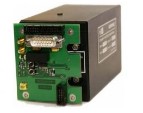
Navigation Systems Receiver module
On the two high-frequency outputs of the receiver board, the signals of the second mark of the navigation receiver and the RF, which are available for the customer`s use, are generated.
When receiving signals from satellites of the GLONASS and GPS radio navigation systems, the board ensures the operation of the RF in the frequency binding mode according to the signals of the second timestamp (the so-called “disciplined” rubidium frequency standard mode) with an error of the actual value of the RF frequency for no more than ± 5.10-12
Ruknar
Nizhny Novgorod
Produced in: Nizhny Novgorod

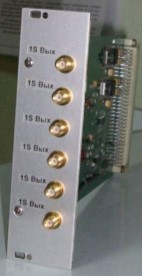
Frequency Synthesizer Module
Designed in the form of a module, standard for RUKNAR CJSC, it can be installed in any modular device of our production, elevating its functionality to a fundamentally new level.
The synthesizer module consists of three independent devices: a frequency synthesizer, a standard signal generator and a time scale generator.
The module has external control via USB 2.0 interface from a personal or tablet computer.
Ruknar
Nizhny Novgorod
Produced in: Nizhny Novgorod
Second Mark Shaper Module
Pulse duration: ......10-15 microseconds
The duration of the leading edge of the pulse:......no more than 20 ns
Pulse amplitude: ...... at least 3V at a load of 50 ohms
Ruknar
Nizhny Novgorod
Produced in: Nizhny Novgorod
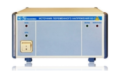
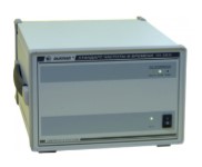
AC voltage source B2-7
The AC voltage source B2-7 is intended to provide devices and equipment with a stabilized AC voltage during the development, production, operation and repair of electronic devices.
Main properties:
Provides protection against overload and short circuits at the output.
Has a light indication:
- overload and short circuit protection tripping;
- incorrect connection of the power supply line to B2-7.
Technical specifications
The nominal value of the output voltage (SKZ) 220 V
The nominal value of the input and output voltage frequency is 50 Hz
Output electrical power, not less than 1000 VA
The main error in setting the output voltage is ± 2.2 V
Additional error in setting the output voltage caused by a deviation of the input voltage by ± 10% from the nominal value of 220 V ± 1.0 V
Additional error in setting the output voltage caused by a change in the load current from the maximum value to zero ± 2.0 V
Instability of the output voltage for any 10 minutes during 8 hours of continuous operation, no more than ± 2.0 V
Operating temperature range from -10 to 50 °C
AC power supply 220 V, 50 Hz
Power consumption, no more than 1200 VA
Overall dimensions, mm 240x128x349
Weight, not more than 6.5 kg
TEKHNOYAKS
Moscow
Produced in: Moscow