Catalog
Search
728 products
View:
- Selected: 1Applying
- Selected: 0Names
- Selected: 0Manufacturer
- Selected: 0Made in
- Selected: 0Additional
View:
728 products
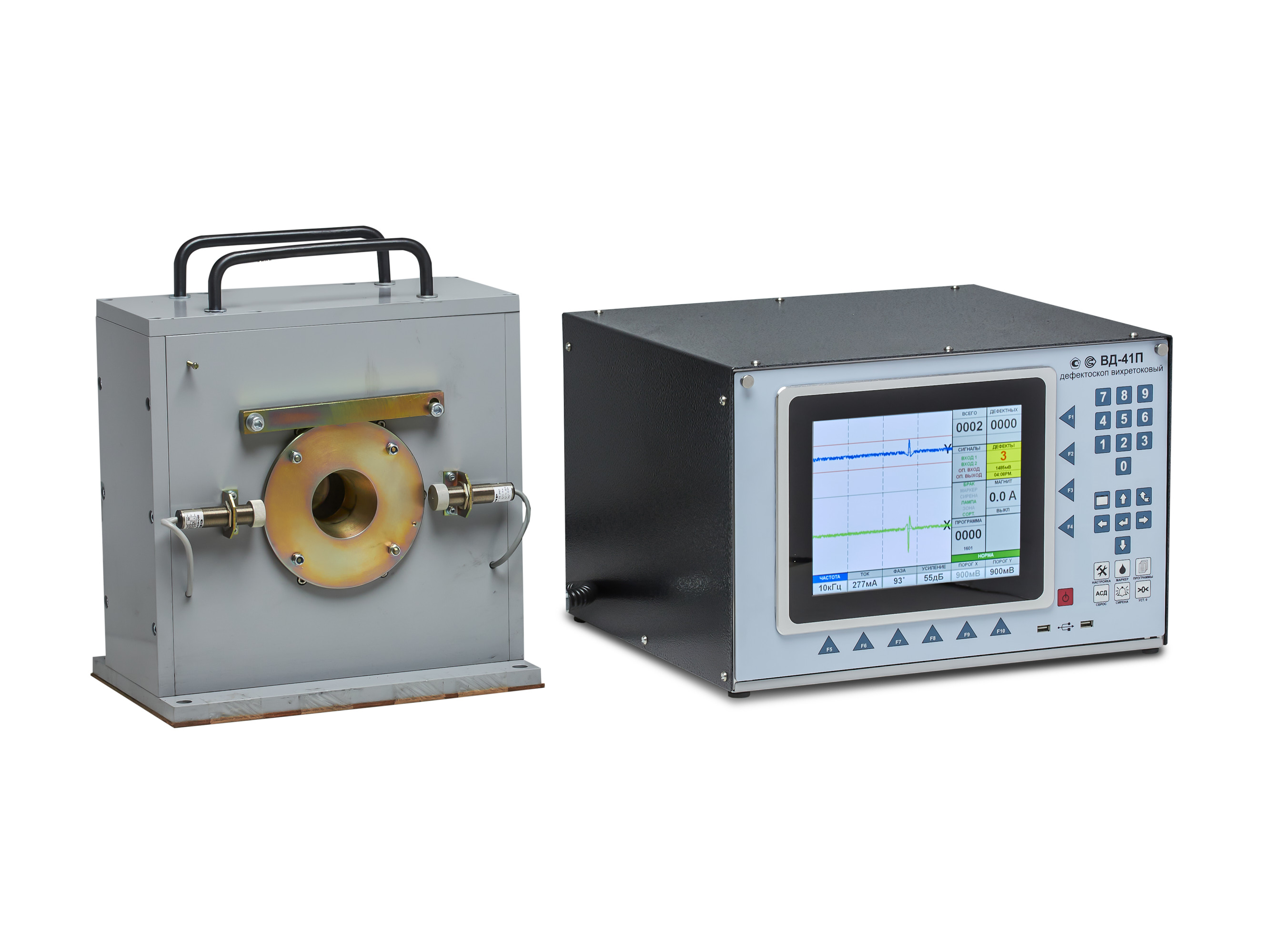
VD-41P Eddy Current Flaw Detector
Scope of application
The VD-41P eddy current flaw detector is designed to work as part of automated quality control lines at pipe-rolling and metal-rolling enterprises with continuous output control of products together with other auxiliary devices: a paint meter, a path sensor, an object presence sensor, an automatic sorter, a demagnetizer.
The device can also be used for input control at machine-building enterprises of the automotive, aviation, oil and gas, and agricultural industries.
Technical specifications:
Control frequencies: 1.0 – 100 kHz.
Control speed (line speed): 0.5 - 5 m/s.
The high-frequency filter is automatically adjustable depending on the speed.
Signal phase adjustment: 0 - 359° .
Converter current adjustment: 50 – 500mA.
Automatic monitoring of the operability of the measuring converter.
Data processing:
- Software adjustable filter.
- Signal evaluation using signal masks:
- circular mask,
- sector masks.
- Sorting by control results.
Display: 10.2” (26 cm) touch LCD (800x600).
Operating system used: WINDOWS® 7.
Dialog language: Russian, other languages (optional).
Applicable eddy current converters: overhead type, through type, sector type.
Interfaces:
- Connector for the converter unit.
- External automation control connector.
- 4 outputs with delay adjustment - "dry contact".
- 2 external information inputs.
- VGA interface for connecting an external monitor.
- USB 2.0.
- Network: Ethernet (TCP/IP).
- Other interfaces on special order.
Power supply: 220 V, 50 Hz.
Operating temperature range: 0 to +40°C.
Type of climatic performance - UHL 4 (i.e. for moderate and cold climate).
Enclosure protection degree: IP 53.
Dimensions, w/h/d: 471 x 285 x 460 mm / can be built in a 19” rack/cabinet.
Weight: approx. 20 kg.
RII MNPO SPEKTR
Moscow
Produced in: Moscow
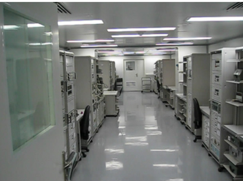
Stationary metrological laboratory
The SML is a stationary object located in the existing production premises of the customer or new buildings built according to the project documentation.
The technical basis of the SML is made up of up to ten automated workstations (APM ST) for SI verification (calibration) and up to three workstations (RM ST) for diagnostics, adjustment and repair of SI.
The ARM ST includes software that allows you to perform SI verification according to a given algorithm and document the results.
All SML equipment is placed on standard basic load-bearing structures (BNC).
At present, design documentation has been developed and the production of automated control systems has been mastered for the complete set of SML of almost all types of radio and electrical measuring devices, pressure and vacuum SI, SI geometric quantities and other SI.
If necessary, the specialists of JSC "NPF "Techno-yaks" are ready to train specialists (ARM operators).
Terms and conditions of financing, development, manufacturing, installation, training of specialists are implemented on the basis of contractual relations with customers
TEKHNOYAKS
Moscow
Produced in: Moscow
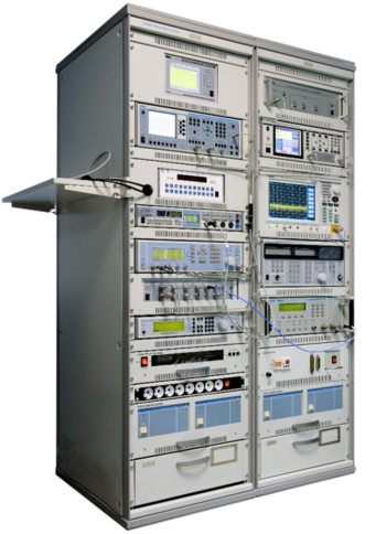
PM-8 verification module
The composition of the PM-8 verification module
Frequency comparator CHK7-1011;
Universal frequency meter Ch3-89;
AC voltage voltmeter VK3-78A;
Universal voltmeter V7-81;
AC voltage calibrator H5-5;
High-frequency signal generator G4-227;
High-frequency signal generator G4-229;
High-frequency signal generator G4-230;
Absorbed power wattmeter M3-108;
Installation for measuring attenuation D1-24/1;
Device for measuring attenuation stepwise D1-25;
Computational modulation meter SK3-49;
The meter-calibrator of the harmonic coefficient SK6-20;
Spectrum analyzer SK4-"Belan 240";
VSWR panoramic meter R2-135;
VSWR panoramic meter R2-137;
A set of exemplary measures of the transmission coefficient H3-7;
Oscilloscope S1-157/4;
DC power supply B5-79/1;
AC power source B2-7 (2 pcs.);
Electronic switch of microwave signals;
PC, printer;
Basic load-bearing structures (BNC).
Technical specifications
Measuring ranges of electrical quantities:
Constant electrical voltage from 3 MV to 1000 V
Alternating electric voltage in the frequency range of 10 Hz ... 2000 MHz from 10 mV to 100 V
Frequency of continuous electromagnetic oscillations from 0.001 Hz to 17.85 GHz
The power of continuous electromagnetic oscillations in the frequency range of 20 MHz ... 17.85 GHz from 0.8 to 10 MW
Attenuation of electromagnetic oscillations in the frequency range 0.1 MHz ... 17.85 GHz from 0 to120 dB
VSWR in the frequency range 0.2 ... 17.85 GHz from 1.03 to 2
Harmonic coefficient in the frequency range of 10 Hz ... 8 GHz from 0.005 to 100 %
The amplitude modulation coefficient in the carrier frequency range of 100 kHz ... 17.85 GHz from 0.1 to 100 %
Frequency deviation in the carrier frequency range of 100 kHz ... 17.85 GHz from 5 Hz to 1 MHz
Phase modulation index in the carrier frequency range 100 kHz ... 17.85 GHz from 1 to 100 radians
Phase shift between two harmonic signals in the frequency range 0.1 MHz ... 17.85 GHz from 0 to 360o
Ranges of reproduction of electrical quantities:
Alternating electrical voltage in the frequency range of 10 Hz ... 2000 MHz from 3 MV to 3 V
Harmonic (sinusoidal) signal at a load of 50 ohms in the frequency range of 0.001 Hz ... 30 MHz from 0.01 to 5 V
Continuous electromagnetic oscillations in the frequency range of 9 kHz ... 17.85 GHz from minus 120 to 13 dBm
5 and 10 MHz reference frequency signal
Attenuation of electromagnetic oscillations in the frequency range 0 ... 3 GHz from 0 to 86 dB
Measurement errors of electrical quantities:
Constant electrical voltage ± (0.0025 ... 16.7) %
Alternating electric voltage in the frequency range 10 Hz ... 2000 MHz ± (0.2 ... 16) %
Frequency of continuous electromagnetic oscillations ± (2·10-7 ... 4·10-3)
Power of continuous electromagnetic oscillations in the frequency range 20 MHz ... 17.85 GHz ± (4 ... 6) %
Attenuation of electromagnetic oscillations in the frequency range 0.1 MHz ... 17.85 GHz ± (0.01 ... 1.2) dB
VSWR in the frequency range 0.2 ... 17.85 GHz ± (3 ... 5) K
Harmonic coefficient in the frequency range 10 Hz ... 8 GHz ± (0.005 ... 6) %
Amplitude modulation coefficient in the carrier frequency range 100 kHz ... 17.85 GHz ± (0.1 ... 9) %
Frequency deviation in the carrier frequency range 100 kHz ... 17.85 GHz ± (0.2 ... 80) Hz
Phase modulation index in the carrier frequency range 100 kHz ... 17.85 GHz ± (0.02 ... 5) radians
Phase shift between two harmonic signals in the frequency range 0.1 MHz ... 17.85 GHz ± (0.01 ... 0.08) o
Errors in the reproduction of electrical quantities:
Alternating electrical voltage in the frequency range 10 Hz ... 2000 MHz ± (0.16 ... 10) %
Harmonic (sinusoidal) signal at a load of 50 ohms in the frequency range 0.001 Hz ... 30 MHz ± (3 ... 5) %;
Continuous electromagnetic oscillations in the frequency range of 9 kHz ... 17.85 GHz ± (0.5 ... 3) dB
5 and 10 MHz reference frequency signal ± (2·10-11 – 2,4·10-10)
Attenuation of electromagnetic oscillations in the frequency range 0 ... 3 GHz ± (0.2 ... 1.4) dB
General technical characteristics:
The area occupied by the module is 6-12 m2
Weight, not more than 550 kg
Power supply voltage from 198 to 242 V with a frequency of (50 ± 0.5) Hz
Power consumption, no more than 3000 VA
TEKHNOYAKS
Moscow
Produced in: Moscow
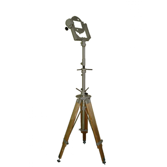
Support-rotary device OPU-1
Technical specifications:
Azimuth rotation angle from 0° to 360° with vernier ± 15°
The angle of rotation according to the angle of the place from minus 30° to plus 90°
The angle of the polarization plane is from minus 5° to plus 95°
The installation height of the axis of the orientation mechanism is from 1.15 to 2.1 m in the version of USHIAI.301554.001 and from 1.4 to 2.35 m in the version of USHIAI.301554.001-01
Smooth adjustment of the height of the axis of the orientation mechanism 0.15 m
In terms of strength under climatic and mechanical influences, the tripod complies with the norms of group 6 GOST 22261-94
The overall dimensions of the tripod are - 2080x2080x2100 mm (USHIAI.301554.001), – 2080x2080x2350 mm (USHIAI.301554.001-01) (shown in the unfolded state at maximum height. The size Ø2080 is the diameter of the circumscribed circle along the vertices of the triangle occupied by the tripod on a horizontal platform)
Operating conditions of the tripod:
ambient temperature from minus 50 to plus 60oC
Tripod weight – 20.5 kg (USHIAI.301554.001), 21.5 kg (USHIAI.301554.001-01)
MNIPI
Minsk
Produced in: Belarus, Minsk
Educational laboratory complex KUL-1
It is intended for use in higher and secondary educational institutions during laboratory workshops on training specialists in engineering and technical specialties and natural science disciplines.
Technical specifications:
Upost.- 0.1 mV - 500 V; Uperem.- 1 mV-300 V (40 Hz-20 kHz)
Ippost. - 0.1 mkA- 2 A; Iperem. - 1.0 mkA - 2 A (40 Hz-1 kHz)
Rpost. - 0.1 Ohm – 20 mOhm
Generation of triangles, pilobr., "meander", sinusoid. signal in the frequency range 0.1 Hz – 1 MHz
Frequency measurement in the range of 0.1 Hz – 1 MHz
The form of the measured signals is sine, pulse
Constant voltage: at a current of 1 A - + 5 V at a current of 0.5 A for each channel - ± 12 V
Adjustable Uppost. at a current of up to 1 A - 0 – 30 V
Dimensions - 170x340x380 mm
Power supply – 230 V, 50 Hz, 200 VA - max.
Weight – 8.0 kg
MNIPI
Minsk
Produced in: Belarus, Minsk
AF011B Microassembly
A high-speed signal limiter amplifier.
Designed for use in electronic counting frequency meters.
Description:
The magnitude of the input signals for selecting the switch input and inverting the signal of the limiter amplifier at a supply voltage of ± 5 V:
- logical "0"
not more than 0.2 V;
- logical "1"
at least 4.8 V.
The value of the input signals of switching on / off the switch at a supply voltage of ± 5 V:
- logical "0"
no more than 3.3 V;
- logical "1"
at least 4.1 V.
The magnitude of the output signals of the switch at a supply voltage of ± 5 V and a load of 300 ohms connected to zero potential:
- logical "0"
from 3.1 V to 3.4 V;
- logical "1"
from 4.0 V to 4.3 V.
The minimum input voltage of the sinusoidal shape in the frequency range from 10 Hz to 200 MHz should be no more than 30 mV.
The maximum input voltage of the sinusoidal shape in the frequency range from 10 Hz to 200 MHz must be at least 1 V.
The value of the supply voltage:
- positive
5±0.2 V;
- negative
-5±0.2 V.
The current consumption should be no more than:
- from a positive power source
110 mA;
- from a negative power supply
35 mA.
MNIPI
Minsk
Produced in: Belarus, Minsk
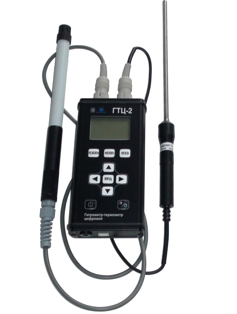
Hygrometer-thermometer digital GTC-2
It is designed to measure relative humidity and air temperature in industrial, warehouse and residential premises, in climatic chambers and technological highways, in open areas (weather stations).
Technical specifications:
Measurement of relative humidity
measuring range (10-100) %
resolution 0.1%
basic measurement error ± 3%
Temperature measurement
measuring range (-60 ... +300) ° C
resolution 0.1 °C
measurement error ± (0.5 - 1.5) ° C
Power supply network adapter, built-in battery
USB 2.0 interface
Weight 1.5 kg
The verification interval is 1 year
MNIPI
Minsk
Produced in: Belarus, Minsk
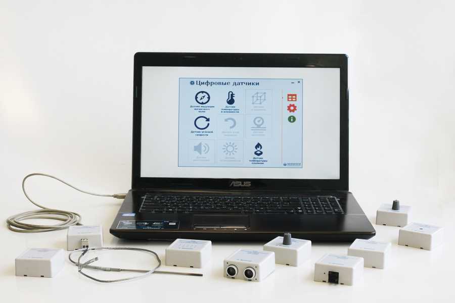
Software and hardware complex with a set of sensors for physics classrooms
The software and hardware complex with a set of sensors for physics classrooms is designed to measure physical quantities during demonstration work on various sections of physics, as well as to perform experimental work on physics.
The set of units of the measuring system is compatible with a PC, has software with an instruction manual.
The sensor kit includes 10 sensors for measuring the following physical quantities:
- temperature sensor DTV-1 (measuring range -200C + 1100 S);
- air humidity sensor DTV-1 (measuring range 10-100%);
- pressure sensor DD-1 (measuring range 0-700 kPa);
- acceleration sensor DUIMP-1 (measuring range - 4 – + 4 g);
- permanent magnetic field induction sensor DUIMP-1 (- 8 – + 8 Gs);
- illumination sensor DSCH-1 (measuring range 1 -60 000 lux);
- distance sensor DR-1 (measuring range 0.04 – 4.0 m);
- angular velocity sensor DUPUS-1 (remote)
(measuring range 0 – 210 0/ c);
- rotation angle sensor DUPUS-1 (measuring range ±3600);
- flame temperature sensor DTP-1 (measuring range 100 – 11000 S).
MNIPI
Minsk
Produced in: Belarus, Minsk
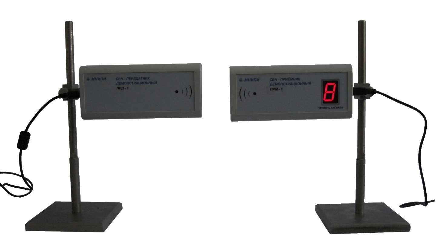
A set of devices for studying the properties of electromagnetic waves
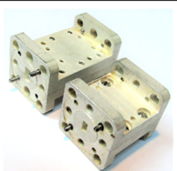
The set of devices includes a microwave transmitter module, a microwave receiver module, a set of devices (metal reflecting screens, a refractive prism, an absorbing screen, etc.) to demonstrate the properties of electromagnetic waves (radiation, absorption, reflection, refraction, interference, diffraction).
Technical specifications:
The wavelength of the microwave transmitter is 3 – 4 cm;
The average value of the energy flux density emitted by the microwave transmitter meets the requirements of the SanPiN 2.4/2.1.8.9-36-2002 (no more than 10 MW/ sq. m.).
Receiver (transmitter) weight, not more than 0.3 kg
Overall dimensions of the receiver (transmitter) 172x25x77 mm
The microwave receiver module has a built-in interface for connecting to a personal computer and provides the ability to display the measured information on the PC screen.
The kit includes an electronic media with software (CD-ROM) to demonstrate the operation of the equipment on the monitor screen of a personal computer.
MNIPI
Minsk
Produced in: Belarus, Minsk
Microassembly RB1S8KN009
Two-channel analog switch with signal summation function
Designed for use in oscilloscopes with a bandwidth up to 350 MHz.
Technical specifications:
The value of the voltage between the outputs of the switch at load resistance RN = (50 ± 2.5) ohms and opening voltages UU1 = (2.0 ± 0.2) V and locking UU2 = (4.2 ± 0.2) V channels supplied alternately to the corresponding inputs (start 1, start 2) of the switches must be:
in the absence of an input signal
from minus 0.1 to plus 0.1 V
with an input signal UC = (0.3 ± 0.05) V supplied to one of the inputs of the open channel
(0.45 ± 0.1) V
with an input signal UC = (0.3 ± 0.05) V supplied to one of the inputs of both open channels
(0.45 ± 0.1) V
MNIPI
Minsk
Produced in: Belarus, Minsk
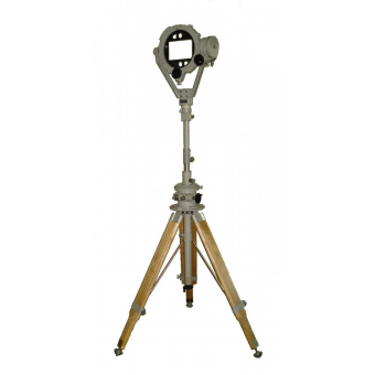
Support and rotary device OPU-2
Technical specifications:
Azimuth rotation angle from 0° to 360° with a reading of 0.1°
The angle of rotation according to the angle of the place from minus 30° to plus 90° with a count of 0.1°
The angle of rotation of the polarization plane from minus 95° to plus 95° with a count of 1°
The installation height of the axis of the orientation mechanism is from 1.35 to 2.5 m. Note – The maximum height is determined when the rack is installed, the smooth lifting mechanism is fully extended and the legs are fully extended to the stop, extended at an angle of 30° to the axis of the azimuth mechanism.
Smooth height adjustment of the axis of the orientation mechanism 0.25 m
In terms of strength under climatic and mechanical influences, the rotary support device (OPU) complies with the norms of group 6 GOST 22261-94
Overall dimensions of the OPU - 1687x2500 (shown in the unfolded state at maximum height. The size Ø1687 is the diameter of the circumscribed circle along the vertices of the triangle occupied by the OPU on a horizontal platform)
Operating conditions of the OPU:
ambient temperature from minus 50 to plus 60 ° C
The mass of the OPU is 19.5 kg
MNIPI
Minsk
Produced in: Belarus, Minsk
