Catalog
Search
728 products
View:
- Selected: 1Applying
- Selected: 0Names
- Selected: 0Manufacturer
- Selected: 0Made in
- Selected: 0Additional
View:
728 products
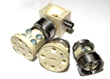
PS-78 (waves.)
Strobe converters are used as input devices of radio measuring equipment: amplifasometers, frequency meters, spectrum analyzers, circuit analyzers, etc.; in systems of synchronization and frequency stabilization of microwave generators, heterodynes, frequency synthesizers.
Basic properties:
Wide frequency range;
Minimal losses and uneven conversion;
High "decoupling" of channels;
Large dynamic range of input signals;
Harsh operating conditions
Operating conditions
Operating temperature range from minus 10 to 50 °C;
Relative humidity up to 98% at a temperature of 25 ° C.
Technical specifications
Frequency range:
• Microwave signal, GHz 37.5-78.33
• heterodyne, GHz 2.0-6.0
• IF, MHz 0-1000
Conversion losses *>, 30-40 dB by the 20th garm.
The power level of the heterodyne, dBm 20-22
Connector type:
• Microwave signal input P-waveguide with transitions to 5,2x2,6 and 3,6x1,8 mm
• 1HR heterodyne input
• IF output two woofer inputs
TEKHNOYAKS
Moscow
Produced in: Moscow
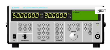
AC voltage calibrator H5-5
The calibrator is capable of operating both autonomously and as part of automated measuring systems with interfaces such as USB, RS-232, IEEE-488 (CPC).
Technical specifications
Ranges of reproduction of alternating electric voltage in the frequency range:
- from 10 Hz to 100 MHz from 3 MV to 3 V
- over 100 MHz to 2000 MHz from 30 MV to 3 V
Errors in the reproduction of alternating electric voltage in the frequency range:
- from 10 Hz to 100 kHz ± (0.066 – 0.8)%
- over 100 kHz to 100 MHz ± (0.85 – 2.5)%
- over 100 MHz to 700 MHz ± (1.5 – 12.7)%
- over 700 MHz to 2000 MHz ± (4.3 -14.0)%
General characteristics:
Operating temperature range from 5 to 40 °C
AC power supply 220 V, 50 Hz
Power consumption, no more than 180 VA
Overall dimensions, mm 495x217x411
Weight, not more than 24 kg
TEKHNOYAKS
Moscow
Produced in: Moscow
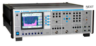
Universal frequency meter Ch3-89
The frequency meter is able to work both independently and as part of automated measuring systems with interfaces such as USB or RS-232.
Technical specifications
Frequency and period of sinusoidal signals (inputs A, B) 0.001 Hz - 150 MHz
Frequency of video pulse signals (inputs A, B) 0.001 Hz - 100 MHz
Frequency of continuous sinusoidal oscillations (input C) (0.1 - 1) GHz
Frequency of continuous sinusoidal oscillations (input D) (1 - 37.5) GHz
Carrier frequency of a continuous signal with frequency modulation (FM) (input D) Fh = (1 - 18) GHz, Fm = 100 Hz-100 kHz; frequency deviation from 10 kHz to 10 MHz
Carrier frequency of a continuous signal with amplitude modulation (AM) (input D) Fh = (1 - 18) GHz, Fm = 100 Hz - 100 kHz; AM factor up to 100%
Carrier frequency of a continuous radio pulse sequence (IM) signal (input D) Fn = (1-37.5) GHz, from 0.15 microseconds to 1ms, Fsl from 100 Hz to 3 MHz, from 2 to 103
Pulse duration 10 ns – 0.1 s
Time interval from -10 to 10 s
The duration of the front, the decay of the pulses is 5 ns - 100 microseconds
Phase difference of two synchronous sinusoidal signals from minus 360° to 360°
The measurement error of the phase difference of two synchronous sinusoidal signals is ± 0.36° (from 1 kHz to 1 MHz) ± 3.6° (above 1 MHz)
Input signal level:
•for sinusoidal signal (inputs A, B) (0.03 - 7.0) V
•for video pulse signal (inputs A, B) (0.1 - 10.0) V
•for a sinusoidal signal (input C) (0.03 - 1.0) V
•for sinusoidal and IM signals (input D) 10 MW (from 1 to 8 GHz); 40 MW (sv. 8 to 18 GHz); 50 MW (sv. 18 to 37.5 GHz).
The nominal frequency value of the reference quartz oscillator is 10 MHz
Relative error in the frequency of the quartz oscillator, no more than ± 2x10⁻⁷ in 12 months
Operating temperature range from 5 to 40 °C
AC power supply 220 V, 50 Hz
Power consumption, no more than 100 VhA
Overall dimensions, mm 496x174x459
Weight, not more than 16 kg
TEKHNOYAKS
Moscow
Produced in: Moscow
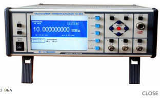
Universal frequency meter Ch3-86A
The frequency meter is capable of operating both independently and as part of automated measuring systems with an interface such as USB, RS-232 or IEEE-488 (CPC).
Technical specifications
Frequency and period of sinusoidal and video pulse signals (input A) 0.005 Hz - 100 MHz
Frequency of sinusoidal and video pulse signals (input to) 0.01 Hz - 100 MHz
Frequency of continuous sinusoidal oscillations (input C) (0.1 - 1) GHz
Frequency of continuous sinusoidal oscillations (input D) (0.6 - 17.85) GHz
Pulse duration 10 ns - 10000 s
The duration of the front, the decay of the pulses is 5 ns - 100 microseconds
Time interval from 0 to 10000 s
The frequency ratio of the two signals is up to 109
The average value of the carrier frequency of the pulse-modulated (IM) signal (input D) (0.6 - 17.85) GHz
Frequency measurement resolution 2x10⁻¹⁰ s/Rng
Phase difference of two synchronous sinusoidal signals from minus 180° to 180°
Measurement error of the phase difference of two synchronous sinusoidal signals ± 0.36° (from 1 kHz to 1 MHz)±3.6° (above 1 MHz)
Input signal level:
•for sinusoidal signal (inputs A, B) (0.03 - 7.0) V
•for video pulse signal (inputs A, B) (0.1 - 10.0) V
•for a sinusoidal signal (input C) (0.03 - 1.0) V
•for sinusoidal and IM signals (input D) 30 MW - 5 MW
Input resistance
•Inputs A, B (50±2.5) ohms; (1±0.1) MOm/100 pF
•inputs C, D (50±2.5) ohms
Nominal frequency value of the reference quartz oscillator 10 MHz
Relative error in the frequency of the quartz oscillator, no more than ± 2x10⁻⁷ in 12 months
Operating temperature range from minus 10 to 50 °C
AC power supply 220 V, 50 Hz; 220 V, 400 Hz
Power consumption, no more than 50 VA
Overall dimensions, mm 229x136x435.5
Weight, not more than 7.5 kg
TEKHNOYAKS
Moscow
Produced in: Moscow
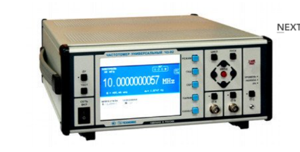
Universal frequency meter Ch3-92
The frequency meter is able to work both independently and as part of automated measuring systems with interfaces such as USB or RS-232.
Technical specifications
Frequency and period of sinusoidal signals (inputs A, B) 0.001 Hz - 300 MHz
Frequency and period of video pulse signals (inputs A, B) 0.001 Hz - 300 MHz
Frequency of continuous sinusoidal oscillations (input C) (0.3 – 37.5) GHz
Pulse duration 10 ns - 1000 s
The duration of the front, the decay of the pulses is 5 ns - 100 microseconds
Time interval from -1000 to 1000 s
Frequency measurement resolution 2x10⁻¹⁰ s/Rng
The range of setting the trigger levels (inputs A, B) from minus 2.5 to 2.5 V
The error of setting the trigger levels (inputs A, B) ± 0.05 V
Input signal level:
• for sinusoidal signal (inputs A, B) (0.03 - 10.0) V
• for video pulse signal (inputs A, B) (0.1 - 10.0) V
• for sinusoidal signal (input C) 50 MW - 5 MW
Input resistance
• Inputs A, B (50±2.5) ohms; (1±0.1) MOm/100 pF
• Input With (50±2.5) ohms
Nominal frequency value of the reference quartz oscillator 10 MHz
Relative error in the frequency of the quartz oscillator, no more than ± 2x10⁻⁷ in 12 months
Operating temperature range from minus 10 to 40 °C
AC power supply 220 V, 50 Hz
Power consumption, not more than 100 VA
Overall dimensions, mm
299x136x436,5
Weight, not more than 8.5 kg
TEKHNOYAKS
Moscow
Produced in: Moscow
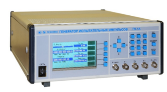
Generator of test pulses G9-1A
The generator is capable of operating both autonomously and as part of automated measuring systems with interfaces such as RS-232 and ITHERNET.
Technical specifications
The range of setting the pulse duration at the outputs:
- τ1 from 100 ns to 10 s
- t2 from 101 ns to 10.1 s
- t3 from 10 ns to 3600 s
The range of setting the time interval between the pulse fronts at outputs t1 and t2 (∆tx) is from 0 to 3600 s
The main error in setting the pulse duration at outputs t1 and t2 ± (δ0 • t1,2 + 1•10-8 c)
The basic error of setting the pulse duration at the output is τ3 ± (δ0 •τ3 + 2 •10-9 s)
The main error in setting the duration of the time interval (∆tx):
∆tx from 0 to 1000 s ± (δ0 •∆tx + 2•10-10 s)
∆tx from 1000 to 3600 s ± (δ0 •∆tx + 2•10-9 s)
Pulse amplitude at outputs τ1 , τ2 and τ3 at a load of 50 ohms, not less than 1.2 V
The nominal frequency value of the reference quartz oscillator is 10 MHz
Relative error in the frequency of the quartz oscillator (δ0 ), no more than ± 2x10⁻⁷ in 24 months
The pulse repetition frequency setting range at outputs τ4 and τ5 is from 0.1 Hz to 300 MHz
The main error in setting the pulse repetition frequency at outputs τ4 and τ5 ± δ0 •F = τ4.5
Pulse amplitude setting range at outputs τ4 and τ5 from 0.05 to 1 V
The main error in setting the pulse amplitude at outputs τ4 and τ5 ± 20%
Fixed values of pulse durations at the output of τ6 1 and 5 microseconds
The basic error of setting the pulse duration at the output is τ6 ± (0.2•τ6 + 3 •10-7 s)
The nominal value of the pulse repetition frequency at the output is τ6 100 kHz
The main error in setting the pulse repetition frequency at the output is τ6 ± δ0 •F = τ6
Fixed values of the pulse amplitude at the output of τ6 minus 10 V; minus 2.5 V; 2.5 V; 10 V
The main error in setting the pulse amplitude at the output is τ6 ± 20%
Operating temperature range from 5°C to 40 °C
AC power supply 220 V, 50 Hz
Power consumption, not more than 100 VA
Overall dimensions, mm 442x160x452
Weight, not more than 10 kg
TEKHNOYAKS
Moscow
Produced in: Moscow
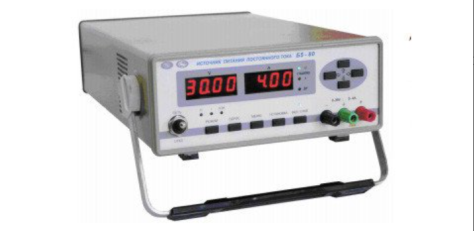
DC power supply B5-80 (81, 82)
The devices are used both independently and as part of automated
systems when working with control from a PC via the RS 232; RS 485 interface.
Technical specifications
Operating temperature range from 5 to 40 °C
AC power supply 220 V, 50 Hz
Power consumption, no more than 400 VA
Overall dimensions, mm 266x105x398
Weight, not more than 8 kg
TEKHNOYAKS
Moscow
Produced in: Moscow
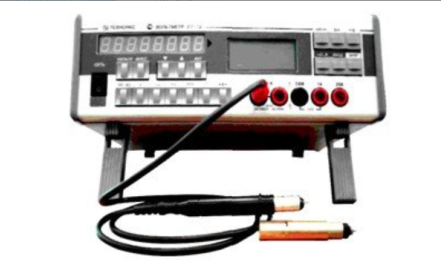
Universal voltmeter V7-79
The voltmeter is capable of operating both independently and as part of automated measuring systems with RS-232 interfaces.
Technical specifications
Measuring ranges of electrical quantities:
- constant electrical voltage from 10 MV to 1000 V
- SCR of alternating electric voltage in the frequency range from 10 Hz to 10 MHz (AC) from 1 mV to 750 V
- RF RF AC voltage in the frequency range from 10 kHz to 1500 MHz (RF) from 10 mV to 1000 V
- DC electric current from 0.1 µA to 20 A
- SCZ of alternating electric current in the frequency range from 10 Hz to 5 kHz from 10 µA to 20 A
- electrical resistance from 10 mOhm to 1 GOm
- frequency of the measured AC voltage from 10 Hz to 1 MHz
Measurement errors of electrical quantities:
- constant electrical voltage ± (0.0028 - 20)%
- SCR of alternating electric voltage in the frequency range from 10 Hz to 10 MHz (AC) ± (0.09 - 15)%
- RF RF AC voltage in the frequency range from 10 kHz to 1500 MHz (RF) ± (1.6 - 66)%
- DC current ± (0.012 - 20)%
- SCR of alternating electric current in the frequency range from 10 Hz to 5 kHz ± (0.11 - 2.35)%
- electrical resistance ± (0.007 - 5.5) %
- frequency of the measured alternating electric voltage ± (0.1 -10.1) %
General characteristics:
Operating temperature range from 5 to 40 °C
AC power supply 220 V, 50 Hz
Power consumption, no more than 20 VA
Overall dimensions, mm 291x110x308
Weight, not more than 4.5 kg
TEKHNOYAKS
Moscow
Produced in: Moscow
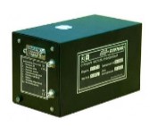
Rubidium frequency standard H1-1013
Its small dimensions, weight, power consumption, and operating time allow it to be widely used as an embedded source of high-stability signals in frequency measuring devices and complexes, telecommunications systems, navigation and communication systems.
Ruknar
Nizhny Novgorod
Produced in: Nizhny Novgorod
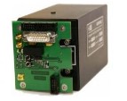
Navigation Systems Receiver module
On the two high-frequency outputs of the receiver board, the signals of the second mark of the navigation receiver and the RF, which are available for the customer`s use, are generated.
When receiving signals from satellites of the GLONASS and GPS radio navigation systems, the board ensures the operation of the RF in the frequency binding mode according to the signals of the second timestamp (the so-called “disciplined” rubidium frequency standard mode) with an error of the actual value of the RF frequency for no more than ± 5.10-12
Ruknar
Nizhny Novgorod
Produced in: Nizhny Novgorod
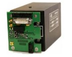
Rubidium Ch1-1014 Frequency Standard with GPS/GLONASS Signal Receiver Module
The signals of the navigation receiver's second mark and the RF available for the customer`s use are generated simultaneously on two high-frequency outputs of the receiver board. In the presence of stable reception of signals from satellites of the GLONASS and GPS radio navigation systems, the board ensures the operation of the RF in the frequency binding mode according to the signals of the second timestamp (the so-called “disciplined” rubidium frequency standard mode) with a relative error of the actual value of the RF frequency of no more than ± 5.0.10-12.
Ruknar
Nizhny Novgorod
Produced in: Nizhny Novgorod
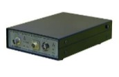
Frequency comparator CHK7-1012
The comparator CHK7-1012 has a communication interface with an external personal computer USB 2.0 and application software for an external PC.
At the request of the customer, the comparator can be supplied complete with a laptop or tablet computer with installed software.
Ruknar
Nizhny Novgorod
Produced in: Nizhny Novgorod
